
STEP has launched the VD8849 dispensing control system, which enables simultaneous programming and visual debugging directly on the PC.
2021-08-27

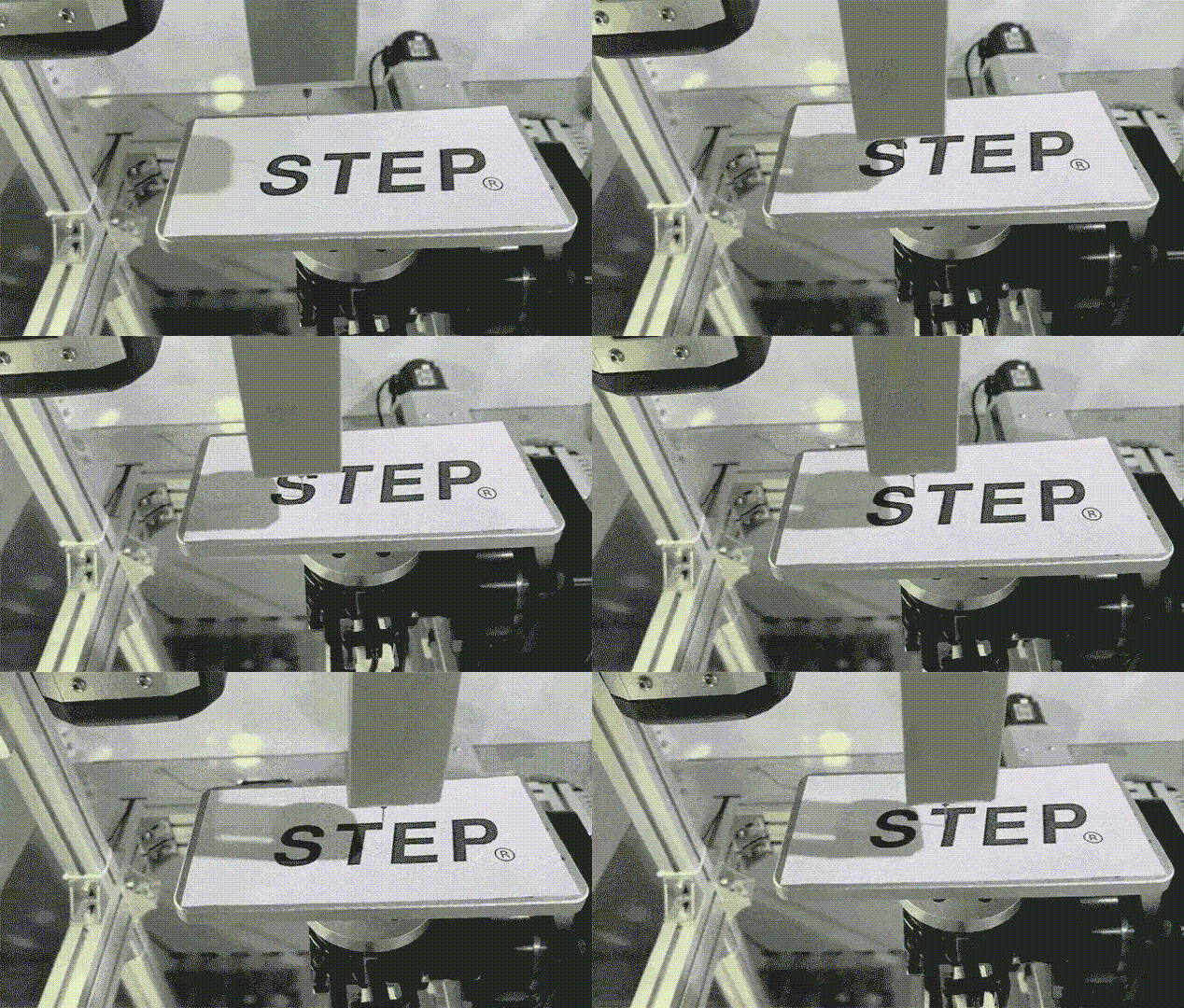
The miniaturization of electronic products and the increasing integration of internal chips have led to an explosive growth in demand for visual dispensing equipment. As the core “brain” of the entire device, the dispensing controller addresses process-related challenges in dispensing operations. By communicating data with machine vision positioning systems, it ensures precise performance even in complex operational environments. In terms of teaching methods, handheld teaching and editing of dispensing paths and flexible, convenient parameter configuration offer great convenience—but... The interaction experience requirements of some users on the PC end should also not be overlooked.
STEP newly launched multi-functional embedded vision dispensing control system. VD8849, Hand-free teach pendant, Using the VDStudio host software, you can simultaneously perform a series of operations on your PC, including programming, visual debugging, diagnostics, and operation log recording.
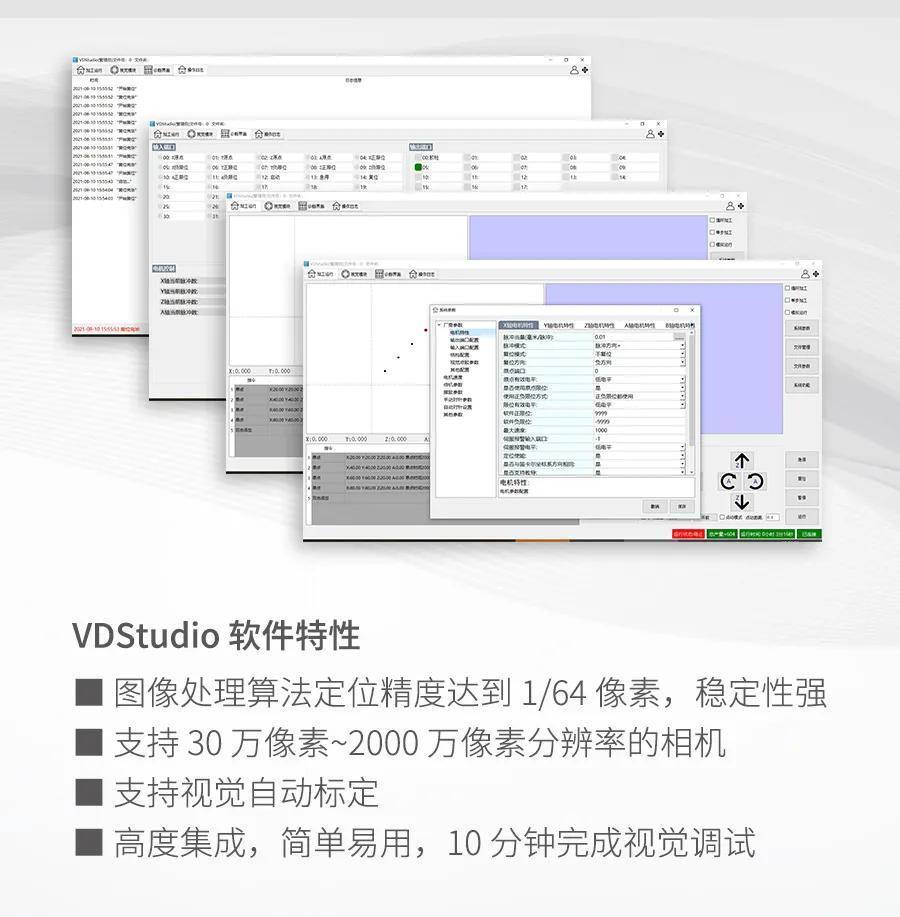
In terms of hardware, the VD8849 represents an enhancement over the previous-generation product. It consists of the AVS2610 vision system and a motion controller based on the OMC system. The devices are interconnected via network communication. The industrial PC in the AVS2610 is used for visual inspection, while the offline motion control card handles motion control tasks as well as operations involving I/O ports. Overall, this configuration ensures high precision in dispensing.

Video: Processing Demonstration of the VD8849 Dispensing Control System
Next, let’s take a closer look at VDStudio—the standout feature of VD8849—block by block, according to its functional components!
# Processing Run
The machining operation interface is used for editing machining files, modifying machining parameters, and selecting machining programs. Parameter settings for the controller—including system parameters, file parameters, and file management functions—are all available in the machining operation interface.
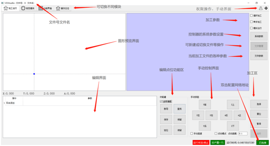
System settings: Parameters used as system-level settings are the same for all files—for example, parameters related to mechanical structures (such as motor characteristics) or basic system configurations (such as port settings)—in short, any parameters that are independent of the processed product.
File parameters: For different processed products, the required processing speeds (trajectory speeds), number of processing passes, and glue-switching times may vary. As a result, each processed product necessitates the setting of different parameters. We can categorize these types of parameters as file parameters. Therefore, by analyzing the characteristics of the parameters, we can pinpoint their exact locations within the file.
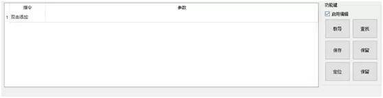
During monitoring operation, you can set either the monitoring mode or the editing mode. You can check “Start Editing” to switch between modes.
Monitoring mode: Only processing can be monitored; the processing points cannot be modified. The background of the monitoring mode is gray:
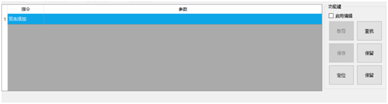
Edit mode: You can edit and process the points. For safety reasons, external signals are invalid in this state. The background of the edit mode is white:
# Visual Module
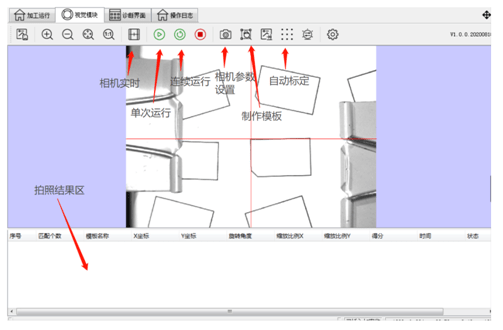
The visual module interface is used to configure the camera, perform nine-point calibration, create visual templates, and monitor captured image data. Visual module interface.
# Diagnosis
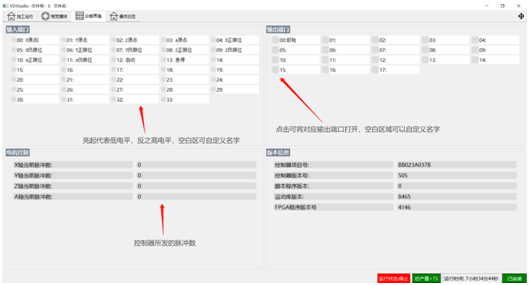
The diagnostic interface is used to monitor input and output ports and view the program version number:
#Operation Log
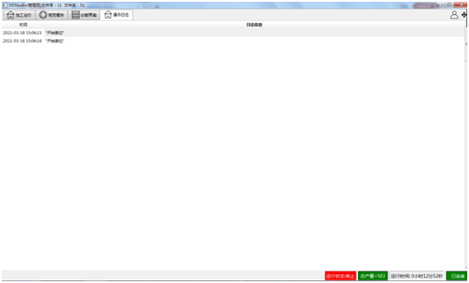
The operation log interface is used to view operation procedures and retrieve historical alarm information.

Contact Us
Email:
market@stepelectric.com
Address:
No. 1560, Siyi Road, Jiading District, Shanghai Municipality