
STEP Inverter | Master-Slave Control and Remote Debugging for Coal Mine Belt Conveyors
2020-12-08

The outbreak of the COVID-19 pandemic this year has caused significant disruptions to production and economic activities across various regions. The scheduled commissioning of three high-voltage variable-frequency drives for main shaft conveyor belts at a coal mine in Ordos, originally set for February 15, has also been affected. If these units cannot be put into operation promptly, it will impact heating demand in certain northern regions. Based on our understanding of the actual on-site conditions and considering the user-friendliness of STEP products, we have decided to adopt an alternative solution—remote commissioning.
1. Condition of the coal mine main shaft belt conveyor system
Original system configuration:
Belt conveyor capacity: 1500 t/h
Tape: width 1400mm, strength ST3150, steel wire rope core
Belt speed: 3.15 m/s
Transportation length: 1110 m
Inclination: +16°
Drive power: 3 × 710 kW, variable-frequency drive
Main motor voltage: 6000V
Upgrade and renovation section: The drive power has been increased from the original 3 × 710 kW to 3 × 1000 kW.
The focus of this upgrade and renovation is to expand production capacity, increase the capacity of the motor and variable-frequency drive systems, and the upgraded belt conveyor system is expected to achieve a throughput of 2,000 t/h.
2. Confirmation of the on-site control plan
① Existing system conditions. The original system at this coal mine also used high-voltage variable-frequency drives for operation. However, as production capacity increased, the original system could no longer meet the demands of production and transportation. The original system employed a separate-control approach: three variable-frequency drives each received individual setpoint signals, and torque balance was achieved by manually adjusting the operating frequencies.
② Renovation objectives: The STEP frequency converter adopts a master-slave control droop function. The software automatically calculates the output torque and achieves automatic power balancing, ensuring that the slave unit’s output voltage and current are consistent with those of the master unit. This truly realizes automatic load balancing for the frequency converter. The system control scheme is shown in Figure 1 below.

Figure 1—Master-Slave Control System Diagram
3. Guide on-site wiring.
① Internal wiring of the frequency converter. Primarily, this involves connecting the internal communication lines of the frequency converter. With remote guidance, the communication system required for commissioning was quickly set up. The instructions for the internal communication connections of the frequency converter are shown in Figure 2 below.
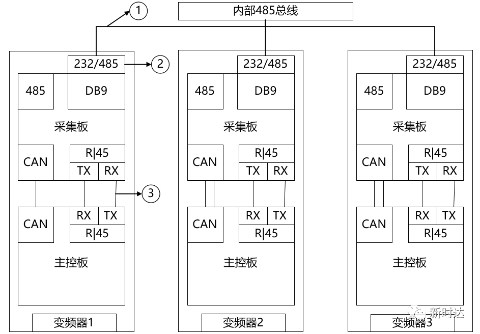
Figure 2—Internal Communication Connection of the Inverter
② External control wiring connection. Extract the control signals required by the user from the drawings, list the signals along with their corresponding wire numbers and terminal numbers based on signal type. Use WeChat video instructions to guide the user in completing the control wiring according to Table 1.
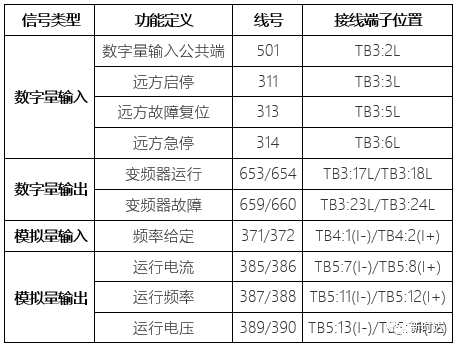
Table 1—External Control Wiring for the Inverter
4. No-load trial run
① Check the high-voltage side wiring. Before commissioning, provide users with WeChat video guidance to confirm and inspect the connection points of the inverter’s incoming and outgoing wires.
② Check the parameter settings of the frequency converter. Most of the frequency converter’s parameters have already been fixed, and the parameters for master-slave control have also been embedded in the multi-drive module, making the inspection process relatively smooth.

Figure 3—Parameter Module for Multi-Motor Drive with Inverter Figure 4—Inverter Parameter Setting Interface
③ Confirmation of control logic
Operating mode: After the operator console sends start/stop commands to the host, while the host executes the start/stop operation, it also controls the start/stop of Slave Unit 1 and Slave Unit 2 via internal communication.
Fault Handling Method: If any one of the three inverters reports a fault and shuts down, the three inverters will perform internal communication to determine the fault and simultaneously initiate an emergency stop and lockout.
Emergency stop procedure: If any one of the three variable frequency drives is manually emergency-stopped, the three VFDs will perform an internal communication-based emergency-stop judgment and simultaneously execute an emergency-stop lockout.
④ Issues Encountered During No-Load Trial Operation and Their Solutions
Host failure: During the first high-voltage energization of the host, an optical fiber fault was reported on all power units in the upstream direction. Upon inspection, it was found that the optical fibers on the master control side had been connected backward—upstream and downstream signals were reversed. After correcting the connection, the issue was resolved.
Slave Unit 1 Failure: During master-slave control interlock, Slave Unit 1 reported a unit blocking fault. After inspecting the communication cable inside the frequency converter and replacing it with a shielded cable, and adding proper grounding measures, the issue was resolved.
5. Load testing and trial operation
Users can perform pre-production loaded tests using coal materials partially produced from underground stockpiles. After directly sending a start command to the host unit from the user console, three frequency converters will drive the main shaft conveyor to gradually and smoothly transport the coal materials produced underground to the unloading area. The loaded test run was successfully completed.

Figure 5—User Conveyor Belt Control Console Figure 6—Inverter Host Operating Interface
6. Officially put into operation
Coal is a fundamental resource essential for ensuring people's livelihoods. During the challenging period of the pandemic, this coal mine responded promptly to the nation’s call and resumed production, with the frequency converters officially put into operation.
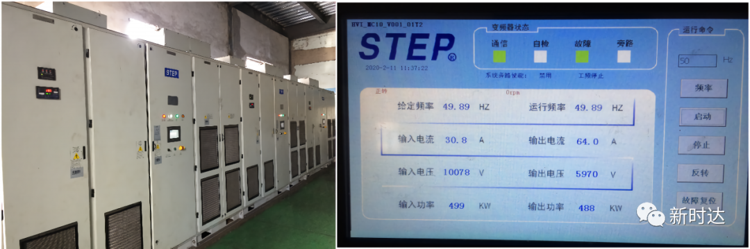
Figure 7—Normal Operation of the Inverter Figure 8—Main Interface for Inverter Operation
Summary
① In this application of the STEP high-voltage frequency converter with constant-torque output, automatic load balancing has been achieved. According to feedback from the user’s site, under the previous manual setting method, the frequency converters exhibited uneven output, often causing the slave unit to be dragged into generator mode and triggering overvoltage alarms. After 1–2 years of use, the belt would stretch and become unusable due to uneven stress distribution. Following the retrofit, automatic load balancing has been implemented, significantly extending the belt’s service life and eliminating the risk of the slave unit’s overvoltage burning out the braking unit.
② The successful completion of this WeChat video-based commissioning guidance has demonstrated the user-friendliness of the STEP high-voltage variable frequency drives. Currently, some of the factory-delivered VFD units have already achieved commissioning-free operation. In the future, STEP high-voltage VFDs will enable features such as online network-based commissioning and real-time fault diagnosis, thereby driving the intelligent transformation of the industrial control industry and opening a new chapter for remote services in special circumstances.

Contact Us
Email:
market@stepelectric.com
Address:
No. 1560, Siyi Road, Jiading District, Shanghai Municipality