
STEP Servo | Turn a die-cutting machine into a banknote-printing machine in seconds—with 32-axis synchronous blade precision.
2020-10-27

1. Equipment Introduction
As a type of light industrial equipment, die-cutting machines produce items that are ubiquitous in our daily lives. Common die-cut products include phone screen protectors, trademark stickers, and medical masks.

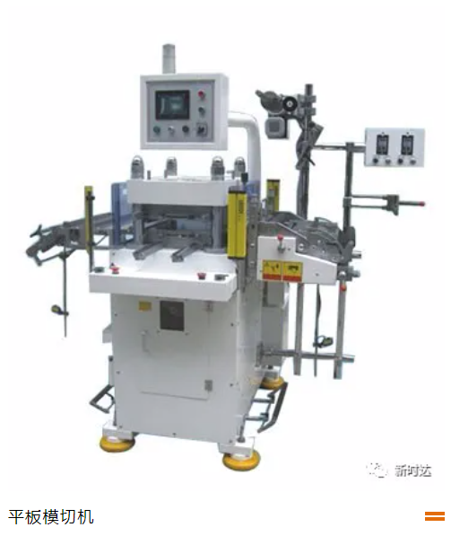
There are two main types of die-cutting machines commonly available on the market: flat-to-flat die-cutting. The simplest flat-to-flat die-cutting machine consists of two shafts—a main drive shaft with a cutting blade and a feed shaft. The main drive shaft powers the two flat plates to move up and down, pressing against each other. The product mold is mounted either on the upper or lower plate, and with the coordinated action of the feed shaft, the machine can complete one processing cycle in a single press. Our Ωs-EN2 series is specially designed for flat-to-flat die-cutting, featuring industry-specific programs tailored for DD motor-driven flat-to-flat die-cutting machines. The entire die-cutting trajectory planning is handled internally by the servo system, ensuring professional efficiency and high performance.
Round-to-round die-cutting, also known as rotary die-cutting, gets its name from the fact that the die is machined from a metal cylinder. The process involves continuous rotation to carry out die-cutting, making it one of the most efficient die-cutting machines available.
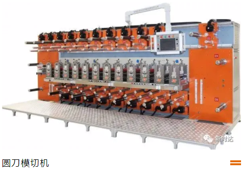
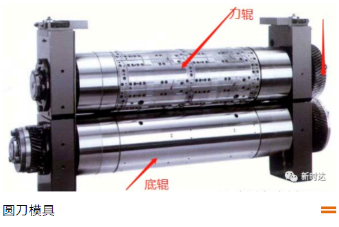
The rotary die-cutting machine is primarily composed of a cutting blade shaft and a winding/unwinding shaft, configured in a 1:2 ratio. The number of workstations depends mainly on the cutting blade shaft. Depending on their specific applications, the cutting blade shaft can be divided into two functions: traction and die-cutting. The traction shaft primarily drives the winding/unwinding shaft to provide precise material feeding, while the die-cutting shaft, by rotating the knife roller and the counter roller at high speed, completes the die-cutting process through pressure.
2. Proposal Introduction
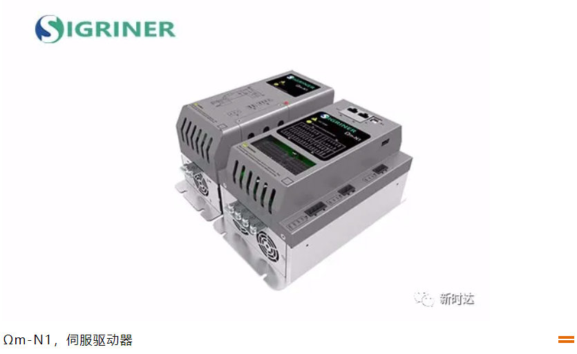
The Ωm-N1 series servo drives used in this solution are multi-axis products launched by the Motion Control Division of STEP. The system employs EtherCAT bus communication. Featuring a DC bus power architecture, these drives support cascaded power supply for multiple drive units and offer flexible customization options for three-axis integrated and four-axis integrated configurations, thereby meeting the requirements of various application scenarios.
3. Product Configuration
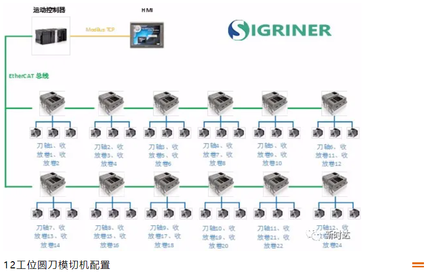
The configuration of this solution is shown in the diagram below (the number of workstations can be freely increased or decreased according to customer requirements). Based on a ratio of 1:2 between the knife spindle and the take-up/reel spindles, the Ωm-N1 model features a three-axis integrated unit, with one servo motor precisely corresponding to one knife spindle and two take-up/reel spindles. On-site testing has demonstrated a maximum synchronous cutting speed of 60 m/min, with a synchronization deviation of the knife spindle within 0.01 mm and a machining accuracy of ±0.05 mm. The probe scanning cycle is 125 μs, ensuring precise compensation of the knife spindle position even during high-speed operation.
Thanks to the torque observation function, it is possible to effectively avoid position synchronization deviations caused by differences in applied forces.
4. Program Features
(1) The Ωm-N1 model features an integrated three-axis design, where a single servo perfectly matches the configuration of one cutting-axis and two retractable axes. Its compact size significantly reduces the installation footprint of electrical equipment.
(2) The high-speed probe function ensures color mark tracking accuracy, enabling precise capture of the color mark position even during high-speed operation and completing position compensation.
(3) Supports setting physical addresses via parameters, eliminating the need to match the write function for Omron controller nodes.
(4) The parameter self-tuning function eliminates the need for customers to spend time on debugging, allowing for direct use upon on-site installation.
(5) Torque observation function ensures precise position synchronization among multiple axes, with on-site installation supporting up to 32 workstations.

Contact Us
Email:
market@stepelectric.com
Address:
No. 1560, Siyi Road, Jiading District, Shanghai Municipality