
STEP Classroom | AS330 Integrated Drive Controller for Escalators – Quick Debugging Guide
2019-01-28

I. Pre-energization Inspection
1. Refer to the instruction manual and the electrical schematic diagram to verify that all connections are correct.
2. Check whether the high-voltage and low-voltage sections are electrically connected. Use the ohmmeter setting on a multimeter to verify that the resistance between different voltage circuits and the resistance to ground should both be ∞.
① The insulation resistance of the three-phase power lines to ground should be greater than 0.5 megohms.
② The insulation resistance of the motor leads to ground should be greater than 0.5 megohms.
③ The insulation resistance between the 220V terminal and ground shall be greater than 0.25 megohms.
④ The insulation resistance of the communication cable to ground shall be greater than 0.25 megohms.
Any of the above items exhibiting short-circuit phenomena must be eliminated.
3. Please carefully check whether the power supply input cable of the control cabinet is correctly connected to the motor wiring. Avoid burning out the integrated drive controller after power-on.
4. Check whether the control cabinet enclosure, motor housing, and safety circuit grounding wires are reliably and safely grounded to ensure personal safety.
Grounding Check: (Please confirm that the following items require reliable grounding.)
① The grounding resistance of the control cabinet should be no more than 4 ohms.
② The motor grounding resistance should not exceed 4 ohms.
II. Check after power-on
1. Turn off the main power switch. If the green light on the phase sequence relay KAP is lit, it indicates that the phase sequence is correct. If the green light is not lit, turn off the main power, swap any two phases of the main power supply, and then re-energize the system.
2. Check whether the voltages at each terminal of the isolation transformer TCO in the control cabinet are within their rated ranges.
3. Assuming the above steps have been performed correctly, close the switch on the power supply control switch. The power supply TPB will be energized, and at the same time, the motherboard will be powered on and begin operating.
III. Parameter Settings
Common parameters of all-in-one machines
F0* Drive Mode 0: 0—Full inverter; 1—Bypass inverter star-delta; 2—Bypass inverter, star-delta only.
F1* Leisure Mode 0.0: No leisure; 1: Leisure at half speed only; 2: Leisure at half speed and leisure stopped.
F2 Fire Escape Ladder 0.0 Non-fire escape ladder, 1 Upward evacuation, 2 Downward evacuation
F3* Rated speed: 500. 100–3000, 0.001 m/s
F4* Maintenance speed: 300. 10–3000, 0.001 m/s
F5* Leisure speed: 150. 10–3000, 0.001 m/s
F6 Normal additional brake release time: 50.0–1000.0, 0.1 s
F7 Leisure Mode Motor Torque Limit: 900. In leisure mode, the motor torque will be protected if it exceeds the set value.
F8 star-corner conversion time: 50.5–500, 0.1 s
F9 fault beep duration: 20.0–10,000, 0.1 s—fault indicating the safety circuit has been disconnected.
F10 Maintenance beep duration: 0.0–50.0, 0.1 s
F11 Reverse entry alarm time: 30.10–1000, 0.1s
F12* Function enabled 0.0–65535
Bit0: Auxiliary Brake
Bit1: Adhesion is reducible
Bit2: Boost Mode
Bit3: Cancel the high-voltage safety circuit
Bit4: Low-speed overcurrent protection mode, default 0
Bit5: Is there a safety acquisition board?
Bit6: Star Corner Startup for the First Time (first power-on or after the elevator has been stopped for more than 6 hours)
Bit7: Reverse photoelectric detection is ineffective when operating at high speed or leisurely slow speed.
Bit8: Direct star-delta start, no star-delta transition.
F13 Automatic refueling interval: 12 hours
F14 single refueling time: 10 seconds
F15* Input Type X0–X15, Normally Open/Normally Closed Settings for Motherboard Input Points
F16* Input Type X16-X31, Normally Open/Normally Closed Settings for Motherboard Input Points
F18* Input Type TX0-TX15: Normally Open/Normally Closed Settings for Safety Acquisition Board Input Points
F19* Input type TX16-TX31: Normally Open/Normally Closed setting for safety acquisition board input points
F21 Fueling single-actuation duration: 10 (unit: 0.1 second)
F22 Fueling single-release time: 20 (unit: 0.1 second)
F23 Same-direction turn to leisure time 100 (unit: 0.1 second)
F23 Reverse turn leisure time 100 (unit: 0.1 second)
F23 Leisure Mode Transition to Leisure Stop Time: 30 (unit: 0.1 second)
F201* Inverter drive mode 0
F202* Motor Type 0: 0 — Asynchronous Motor, 1 — Synchronous Motor
F203* Rated power of the motor. Refer to the nameplate of the main unit.
F204* Rated current of the motor. Refer to the nameplate of the main unit.
F205* Rated frequency of the motor. Refer to the nameplate of the main unit.
F206* Rated speed of the motor. Refer to the nameplate of the main unit.
F207* Motor rated voltage: 380
F208* Number of motor poles: 4 (120 × rated frequency of the main unit / rated speed of the main unit)
F209* Motor rated slip frequency: 1.40
ES.11 Common Parameter Settings for the Security Monitoring Panel
F00* Input type X0-15, X13 is forcibly set to normally closed.
F01* Input type X16-31
F02* Rated speed 1,500, 0.001 m/s
F03* Rated speed 2,500, 0.001 m/s – typically not used
F04* Maintenance rated speed: 300, 0.001 m/s
F05* Leisurely slow speed 150, 0.001 m/s
F06* Number of pulses per revolution: 65, number of main drive gears
F07* Running distance per lap: 2100.001 m, main drive circumference
F08* Stepless distance without pulses: 600, 0.001 m—distance between two step signals
F09* Armrest circumference: 300, 0.001 m
F10* Handrail wheel pulse count: 2, 1–30
F11 Speed measurement with a 5-second delay
F12 low-speed protection delay—generally do not modify.
Note: Usually, you only need to set the parameters marked with an asterisk (*).
4. Maintenance and Operation
1. Insert the maintenance handle into the maintenance socket located in the control cabinet or the lower junction box.
2. The safety circuit is functioning properly. Remember not to short-circuit the safety circuit.
3. The sensor is properly installed and wired correctly.
4. The operator should ensure that both the all-in-one machine and the security monitoring panel are in “Maintenance” mode.
5. Press the up (down) button on the maintenance handle, and the escalator should run at the preset maintenance speed in the up (down) direction.
When the escalator is running in the upward or downward direction, you need to check whether its running direction is correct. If the direction is incorrect, first verify that the wiring of the up and down buttons is properly connected. If the wiring is correct, simply modify the motor phase sequence parameter F234 (change 1 to 0).
6. When the escalator is running slowly either upward or downward, pay close attention to the operating status of the safety monitoring panel and the signal feedback from the sensors. In case of a fault, the safety monitoring panel will forcibly disconnect the safety circuit. At this point, you should check for the fault on the safety monitoring panel and address it according to the prescribed troubleshooting procedures.
6.1 Installation of the Main Drive Wheel Sensor
① Installation location
The sensing surface of Sensor A is aligned directly with the center of the main drive wheel’s gear.
The sensing surface edge of Sensor B is aligned directly with the center of the main drive wheel’s gear.
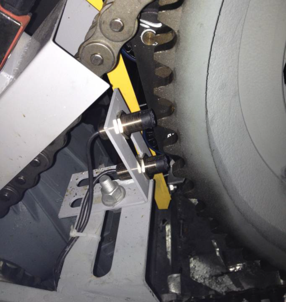
② Detection distance: Determined by the sensor model. The two sensors should be equidistant from the gear. Depending on the selected model, the detection range typically falls within 2 mm ≤ L ≤ 6 mm (determined by the sensor model).
③ Notes: If the installation position of the main drive wheel sensor is inaccurate, faults such as escalator speed dropping below 80%, exceeding 120%, reverse rotation of the escalator, or phase loss in phases A and B may frequently occur.
6.2 Installation of Step Missing Sensors
① Installation Location: The step-loss sensor shall be installed at the upper and lower terminal stations. To comply with national standards, the manufacturer needs to determine the installation location based on the overall elevator performance. Generally, the detection point should take into account the requirements for stopping distance and ensure that the sensor can detect a missing step before it exits the comb plate.
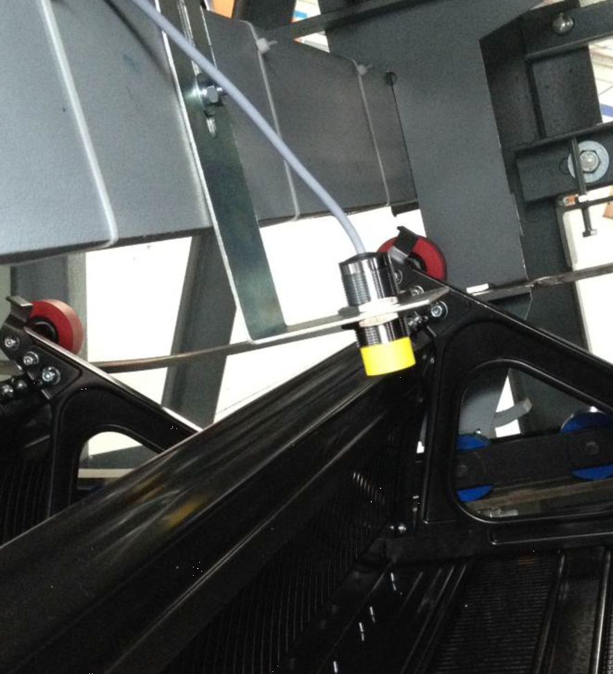
② Detection distance: Determined by the sensor model. The two sensors should be equidistant from the gear. Depending on the selected model, the detection range typically falls within 10 mm ≤ L ≤ 35 mm (to be confirmed based on the sensor model).
③ Notes: For the safety monitoring board parameters, set F08 to a step width that is 1.2 to 1.5 times the actual step width.
6.3 Installation of the Handrail Speed Sensor
① Installation location: Typically installed on the handrail belt drive wheel side in the lower machine room, one on each side, to detect the speed of the handrail belt separately.
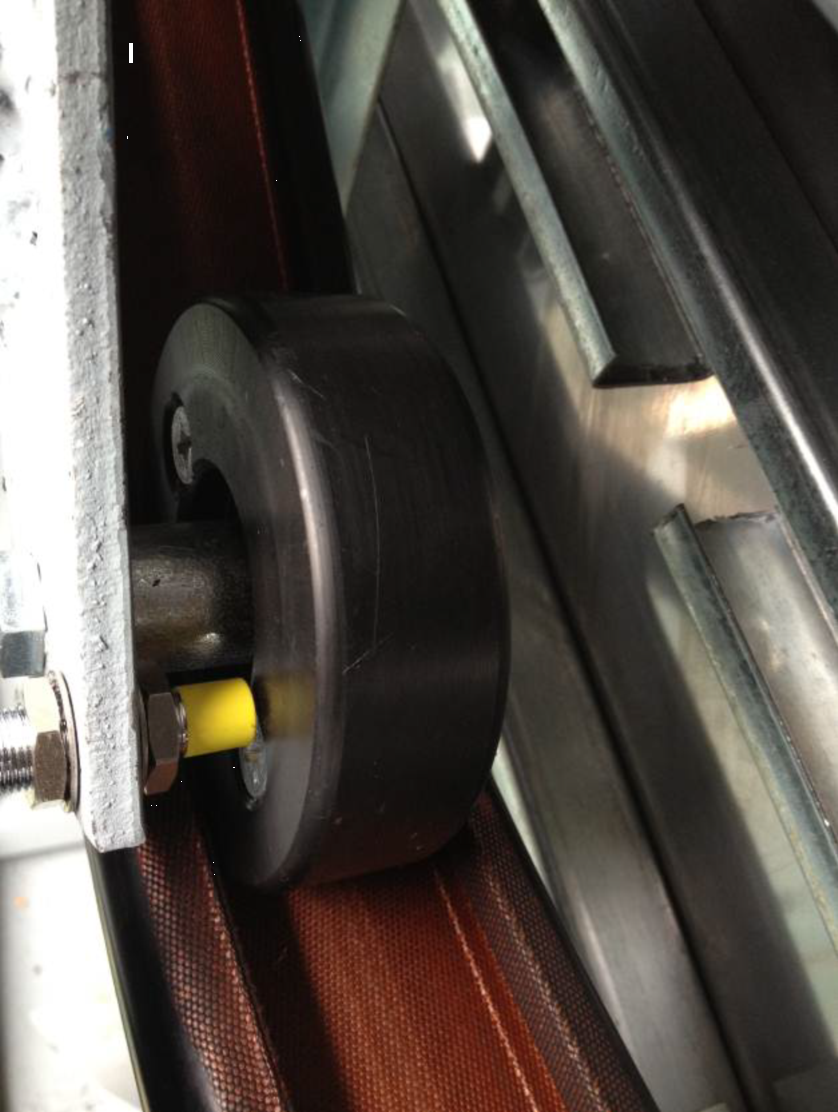
② Detection distance: Determined by the sensor model. The two sensors should be equidistant from the gear. Depending on the selected model, the detection range typically falls within 2 mm ≤ L ≤ 4 mm (to be confirmed based on the sensor model).
③ Precautions: The running speeds of the left and right handrails must be adjusted to be essentially identical.
V. Express Train Operation
① Insert the escalator maintenance handle and plug the normal operation plug into the maintenance socket.
② Use the handheld programmer to check that both the all-in-one machine and the security monitoring board display “Automatic,” indicating that the system has entered normal operating mode.
③ Start the escalator by giving a command via the upper and lower key switches.
VI. Common Fault Codes and Troubleshooting for All-in-One Machines
01 Contactor sticking (not pure frequency conversion). When the holding brake, star-type contactor, angular contactor, up-going contactor, and down-going contactor all have no output, the stick detection still generates a signal.
02 Inverter contactor failure (not a pure inverter). The input and output of the inverter contactor are inconsistent.
03 Power-frequency contactor failure (not purely inverter-based). The input and output of the power-frequency contactor are inconsistent.
04 Braking switch failure. The output and detection of the braking switch are inconsistent.
05 Safety circuit relay failure. The safety high-voltage circuit and the safety circuit relay are inconsistent.
06 Additional brake switch failure. The additional brake switch cannot be turned on.
07 Additional brake relay failure. The input and output of the additional brake relay are inconsistent.
08 Temperature fault. Temperature alarm input is present.
10. Inverter communication failure. There is no communication between the motherboard and the inverter. Check whether the board is securely installed and whether the power supply voltage is stable.
11 The drive chain has broken. The chain-break switch has been activated.
12 Oil level detection failure. Check whether the oil cup is empty.
13. The entrance photoelectric sensor is damaged. Although the escalator load has reached normal levels, the entrance photoelectric sensor has consistently failed to detect any activation.
14 Contactor brake failure (pure VFD). The input and output of the brake contactor are inconsistent.
15. Output contactor 1 fault (pure VFD). The input and output of output contactor 1 are inconsistent.
16. Output contactor 2 fault (pure VFD). Input and output of output contactor 2 are inconsistent.
17. Mode exception switching. During operation, maintenance triggers automatic switching.
69 Parameter not initialized; please reset the control parameters.
71 Module overcurrent protection. Check the host parameter settings and ensure that the brake is reliably released.
74 Brake unit failure. The external brake resistor circuit is short-circuited; check the wiring of the brake resistor.
75. Fuse blown fault. The fuse blew due to excessive current.
76 Output torque overload. Check the input power supply, motor stalling, or sudden and severe changes in load to prevent motor stalling.
78 Overvoltage on the DC bus. Check the configuration and wiring of the braking resistor.
79 Undervoltage on the DC bus. Check whether the three-phase input power supply is too low and whether the wiring connections are loose.
99 Input phase failure. Check the grid voltage for abnormality on the input side.
102 Grounding protection. In case of wiring errors or correction of incorrect wiring, perform an insulation test on the motor against ground.
114 Charging relay failure. The charging relay is damaged, or the three-phase input power voltage has momentarily dropped by more than 30V.
6000+I The i-th switch in the safety circuit is open. Check the wiring of the safety circuit.
7. Common Fault Codes and Troubleshooting for the Security Monitoring Board
31 The real-time clock is damaged. Check whether there is any debris on Y2 on the board; after cleaning it, power it back on. If the issue persists, please submit the unit for manufacturer’s repair.
32 Redundancy detection error. Check whether the power supply is stable at 24V. Re-power the device. If the issue persists, please submit it to the manufacturer for handling.
33 Parameter CRC error. The parameter has not been set. Please reset all parameters, then power off and power on again. If the fault persists, please submit the issue to the manufacturer for handling.
34 CRC error due to a fault. Press the reset button and power on again.
35 The parameter is not appropriate. Check whether the parameter settings are reasonable.
36 Power supply voltage fault. Check whether the power supply voltage is 24V.
37 Safety relay failure. Hardware damage—please submit the issue to the manufacturer for handling.
38 The overspeed exceeds 120%. Check whether the parameters are set correctly, verify that the escalator is not overspeeding, and confirm that the X0 and X1 signals are functioning properly.
39 The overspeed exceeds 140%. Check whether the parameters are set correctly, verify that the escalator is not overspeeding, and confirm that the X0 and X1 signals are functioning properly.
40 The speed is below 80%. Check whether the parameters are set correctly, verify that the escalator is not running too slowly, and confirm that the X0 and X1 signals are functioning properly.
41 AB is connected in reverse. Check whether X0 and X1 are connected in reverse, and verify that the host’s speed-sensing switch is installed in the correct position.
42 The speed has dropped abnormally. Check whether, with the mainboard still running and inputs present, the elevator speed has fallen below the leisure speed. Also, verify that the signals from X0 and X1 are functioning properly.
43 The drive chain has broken. Check whether the chain-break switch has activated, and verify that the input signal to X15 and the NO/NC settings of X15 are correct.
44 The parking brake distance is too long. Check whether the parking distance meets the national standard, and verify whether there is jitter in the signals X0 and X1.
45 Additional brake failure. Check whether the input-output relationships of Y1, Y3, X11, and X12 are incorrect.
46 Steps missing. Check whether X2 is operating normally.
47 Missing step. Check whether X3 is operating normally.
48 The inspection cover is missing.
① Check whether X10 or X18 and their corresponding switches have operated.
② Check whether the inspection and maintenance cover switch has operated.
49. The inspection cover switch is malfunctioning.
① Check whether there are any inconsistencies in X10 or X18.
② Check whether the inspection and maintenance cover switch has operated.
50 The service brake does not release. When checking during parking, verify whether the parking brake switch cannot close.
51 The service brake fails to engage. During startup, check whether the brake release switch can open.
52 Left armrest belt is under speed.
① Check whether the speed switch on the left armrest is functioning properly.
② Check whether the number of pulses and circumference setting for the handrail wheel are correct.
53 The left handrail is overspeeding. Check whether the pulse count and circumference settings for the handrail wheel are correct.
54 Right handrail belt speed insufficient.
① Check whether the speed switch on the right armrest is functioning properly.
② Check whether the number of pulses and circumference setting for the handrail wheel are correct.
55 The right handrail is overspeeding. Check whether the pulse count and circumference settings for the handrail wheel are correct.
56 The up/down and running statuses are inconsistent. Check whether the running status (X6) and the up/down input signals (X7, X8) are functioning properly.
57 The elevator slides down when stopped.
① Check whether X0 and X1, the main wheel speed switches, are jittering.
② Check whether the escalator is slipping.
58. The two-channel I/O is inconsistent. Check whether there are any foreign objects near the input ports on the board (note that there may also be objects on the back side). After cleaning the board, power it on again. If the fault persists, please submit a report to the manufacturer.
59 AB phase missing. The host’s speed sensor has lost the signal from either phase A or phase B.

Contact Us
Email:
market@stepelectric.com
Address:
No. 1560, Siyi Road, Jiading District, Shanghai Municipality