
Introduction to the Main Interface of the New-Time Teaching Device upon Power-On
2024-12-03

This article primarily introduces the functions and operations of the main interface of the STEP robot teach pendant, enabling you to quickly familiarize yourself with the teach pendant’s power-on procedures, commonly used buttons, distinctive language features, and shortcut key functions.
01|Power On and Log In
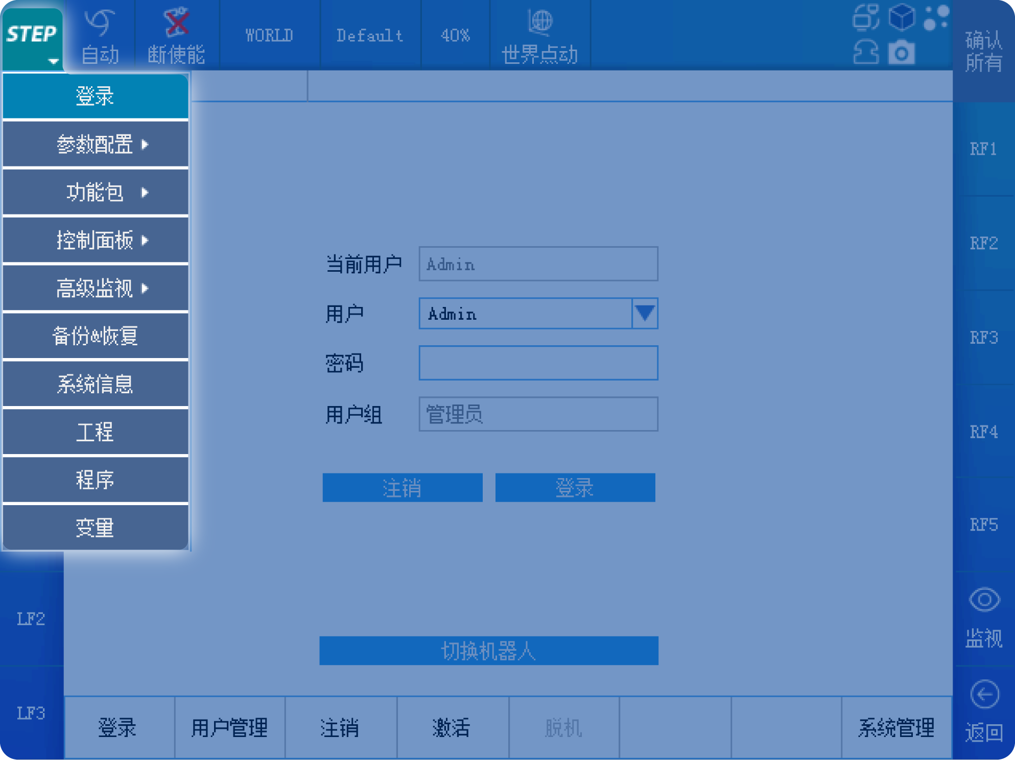
The boot-up interface is shown in the figure below. The default login password for the STEP robot teach pendant is 123. Before logging in, most button names on the touchscreen are grayed out and unresponsive. After logging in, most button names turn white and become responsive.
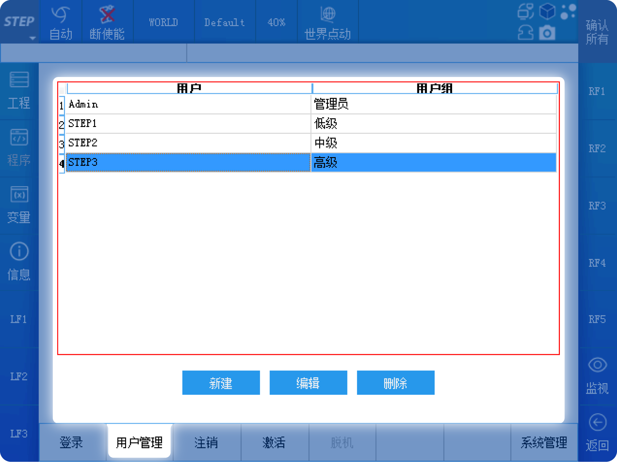
User management allows you to set users at different levels, each with varying operation permissions. This prevents unauthorized modifications to the program or accidental changes to its code.
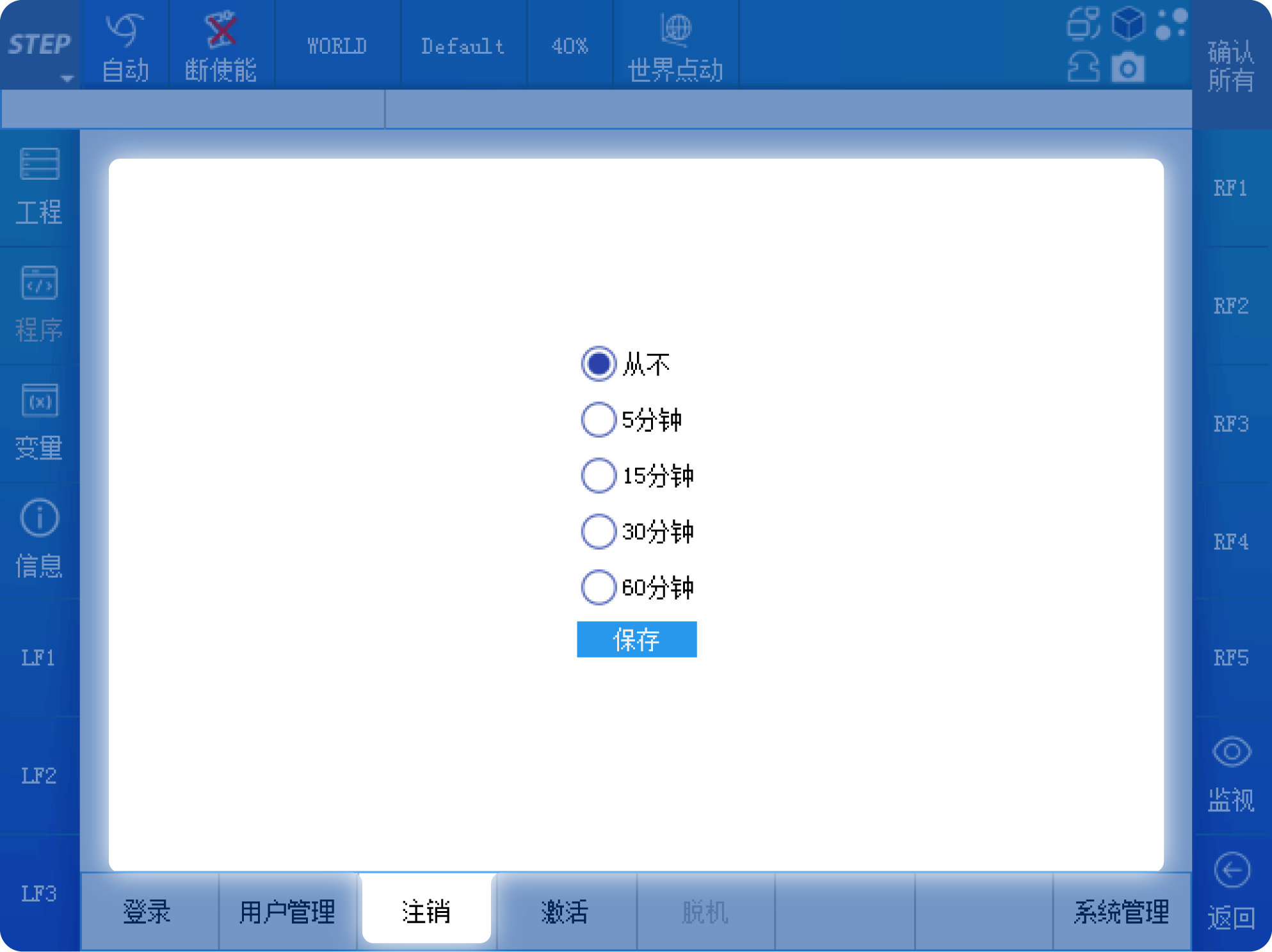
You can set an automatic logout time for logoff. If the teach pendant remains idle for the specified duration, the currently logged-in user will be automatically logged off.
The activation interface is, by default, permanently activated. You can also lock the system and set a usage period. Once the period expires, the robot system will be locked and become inoperable, requiring an unlock before it can be used again.
02|Introduction to the Status Bar
2.1: Introduction to the menu on the left side of the status bar
The topmost row is the status bar. The STEP button on the far left serves as the menu key, containing all the function menus available on the teach pendant. The remaining buttons display the robot’s current status and can also be used to switch between different states.
After you click the menu, a first-level submenu will pop up, containing Login, Parameter Configuration, Feature Packages, Control Panel, Backup & Restore, System Information, Projects, Programs, and Variables. Submenus marked with a “>” symbol indicate that they have second-level submenus as well.
The descriptions of the buttons in the status bar are as follows.
▌Operating Mode
There are three modes available: manual, automatic, and external automatic. In manual mode, you can control the rotation of each axis or the linear motion and orientation changes at the end-effector using the physical buttons on the right side of the teach pendant. In automatic mode, you can run programs that have been pre-programmed by the user. In external automatic mode, the robot’s program can be controlled via external signals, such as those from an external control box or a PLC.
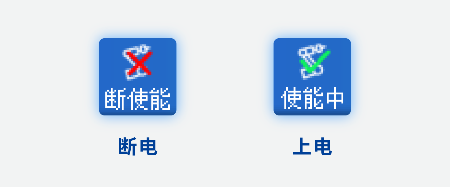
▌Enabled status
Used to indicate whether the servo is powered on (enabled); the servo’s power-on and power-off can be controlled via a button.
▌Reference Coordinate System
Used to display the coordinate system within the current robot system. The coordinate system can be set via buttons or in the program.
▌Tools
Used to display the tools currently configured within the robot system. You can set the tools via buttons or in the program.
▌Speed
Used to display the current running speed of the robot. The speed can be set via buttons or in the program.
▌Manual Coordinate System
When the “Operation Mode” is set to “Manual,” this refers to the coordinate system used as the reference for robot motion. Two commonly used coordinate systems are the joint coordinate system and the world coordinate system. When the joint coordinate system is selected, you can independently control the rotation of the robot’s axes 1 through 6. When the world coordinate system is selected, you can control the robot’s end-effector’s linear motion or orientation changes.
2.2: Introduction to the icons on the right side of the status bar
On the far right of the status bar, there are five more icons, each with the following meanings:
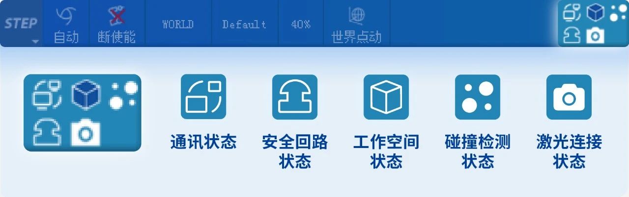
▌Communication Status
Displays the communication status between the teach pendant and the robot controller.
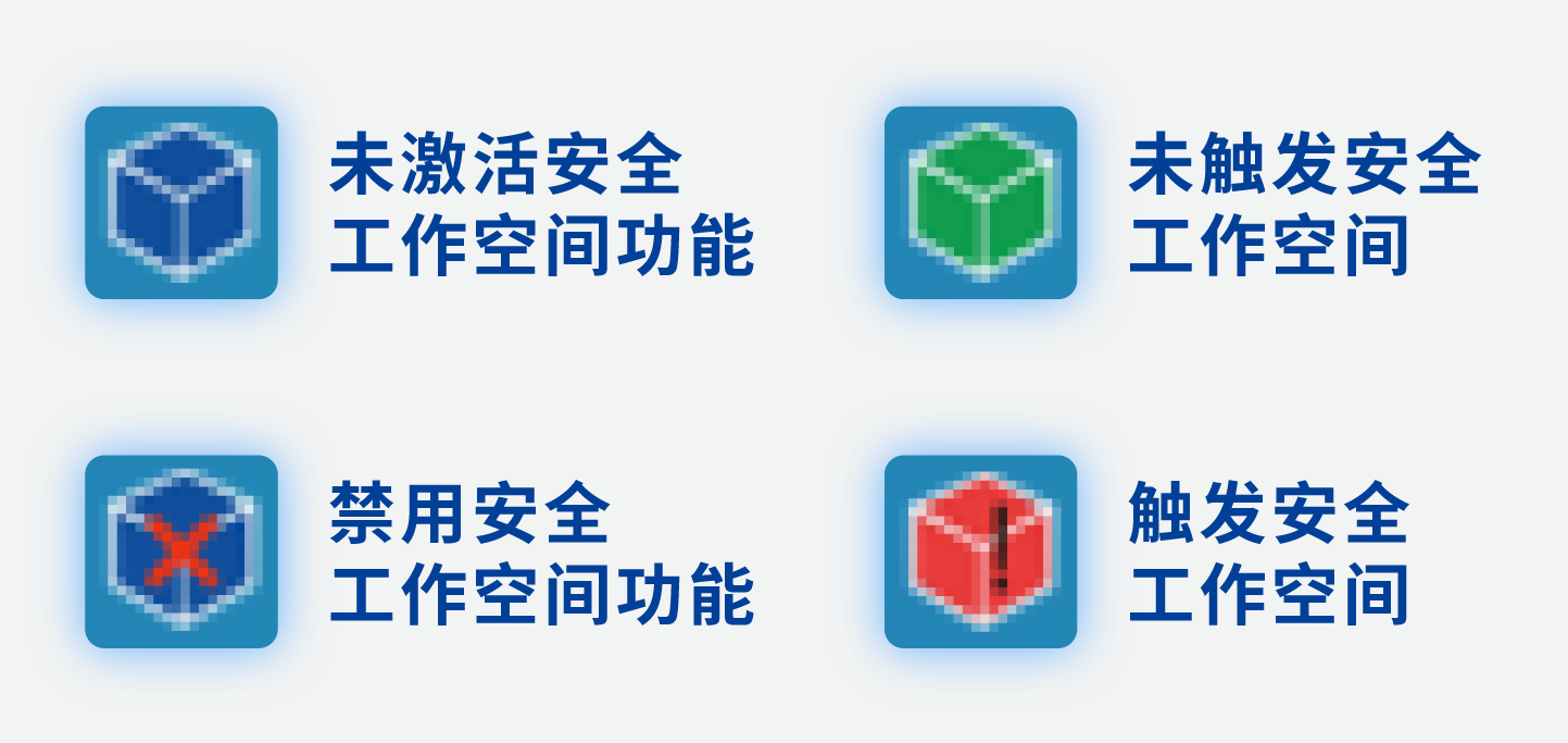
▌Workspace Status
The workspace has four states: the security workspace feature is not activated, the security workspace has not been triggered, the security workspace has been triggered, and the security workspace feature is disabled.
▌Collision Detection Status

▌Safety Circuit Status
When the emergency stop button is pressed or the access control switch is opened, “Safety circuit disconnected” will be displayed.

▌Laser Connection Status
When the laser connection status icon displays “Laser Working,” it indicates that laser scan data is being received.

2.3: Introduction to the display bar below the status bar
Below the status bar, from left to right, are the currently loaded program, the current alarm information, and the clear alarm button.
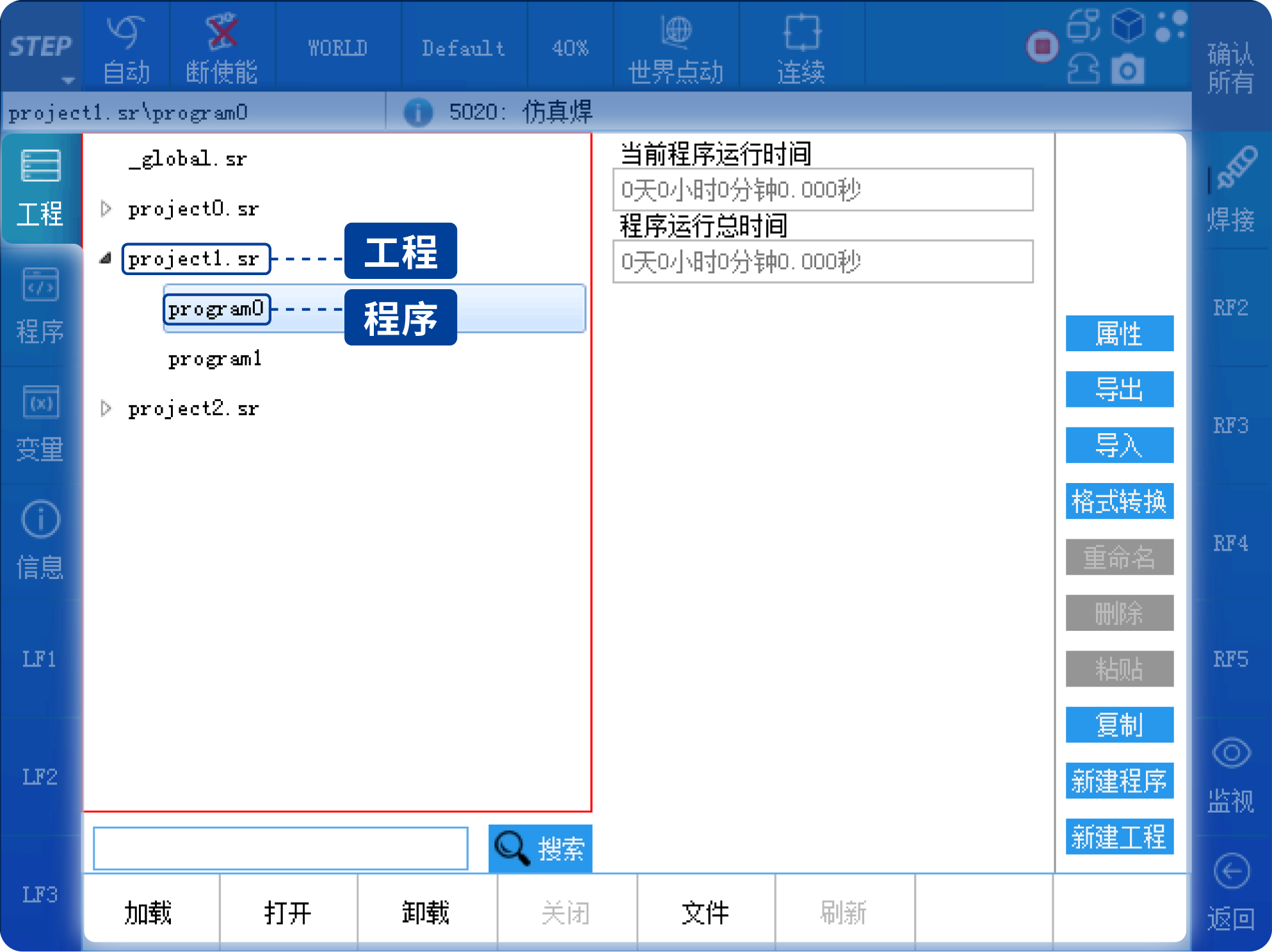
03|Engineering and Variable Management
Click the first button at the top left, labeled “Project,” to display the system’s current project directory. Multiple programs can be created under a single project.
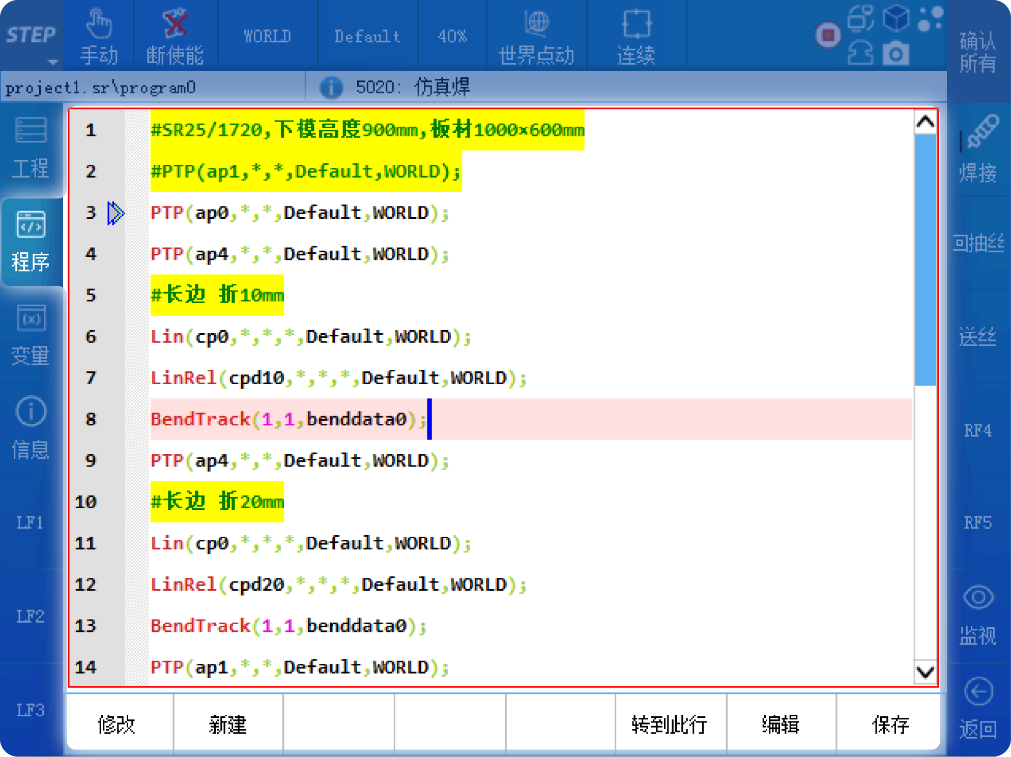
Click the “Program” button to display the currently loaded program.
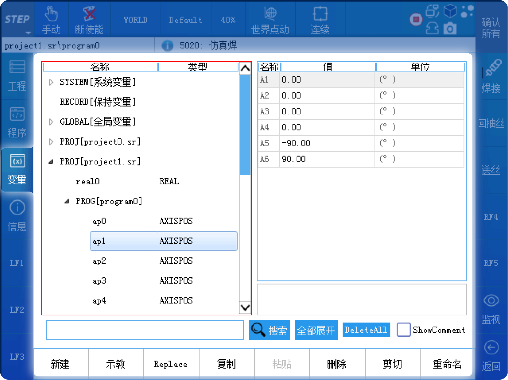
Click the “Variables” button to display all system variables, and support variable search and editing.
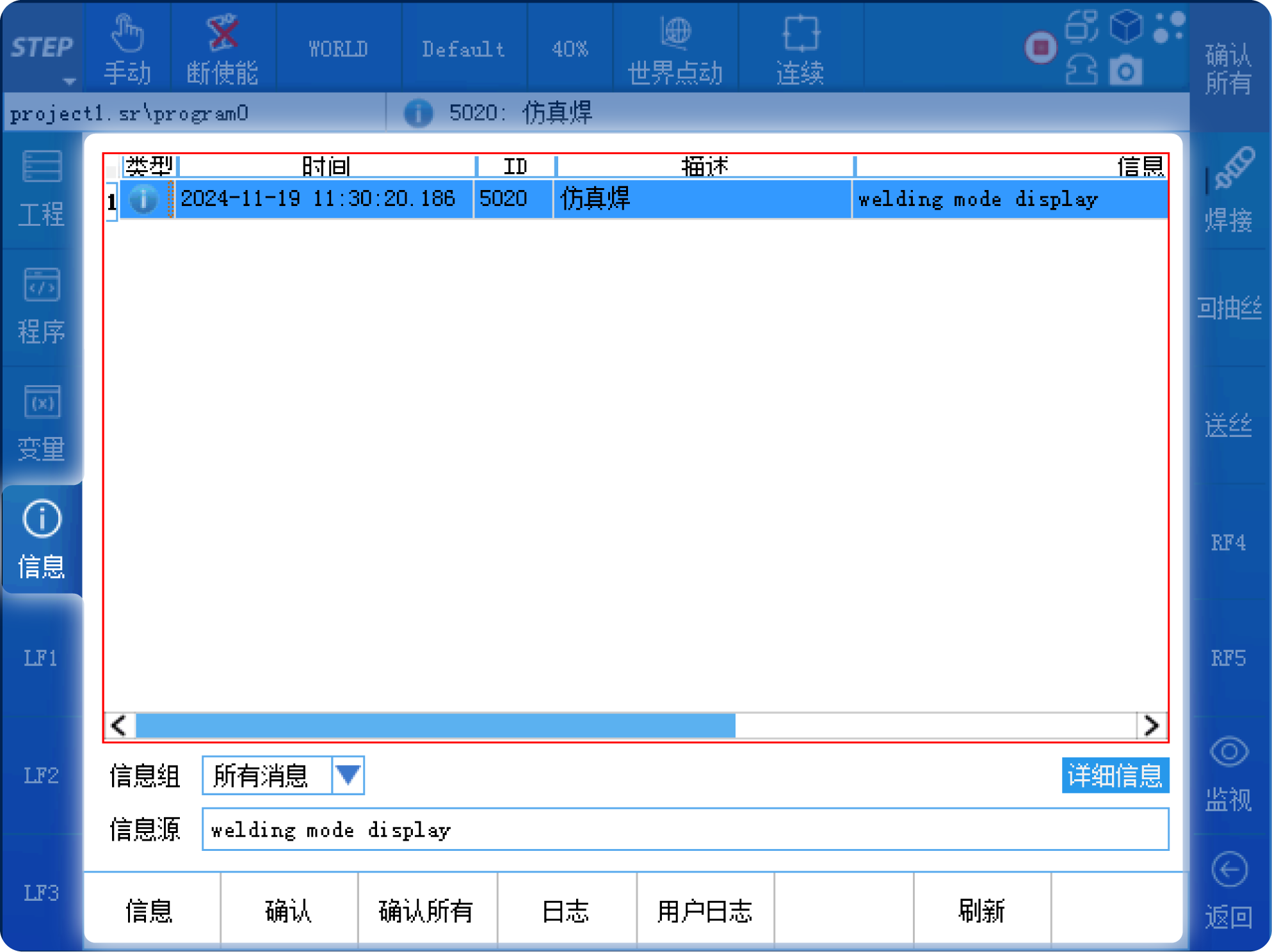
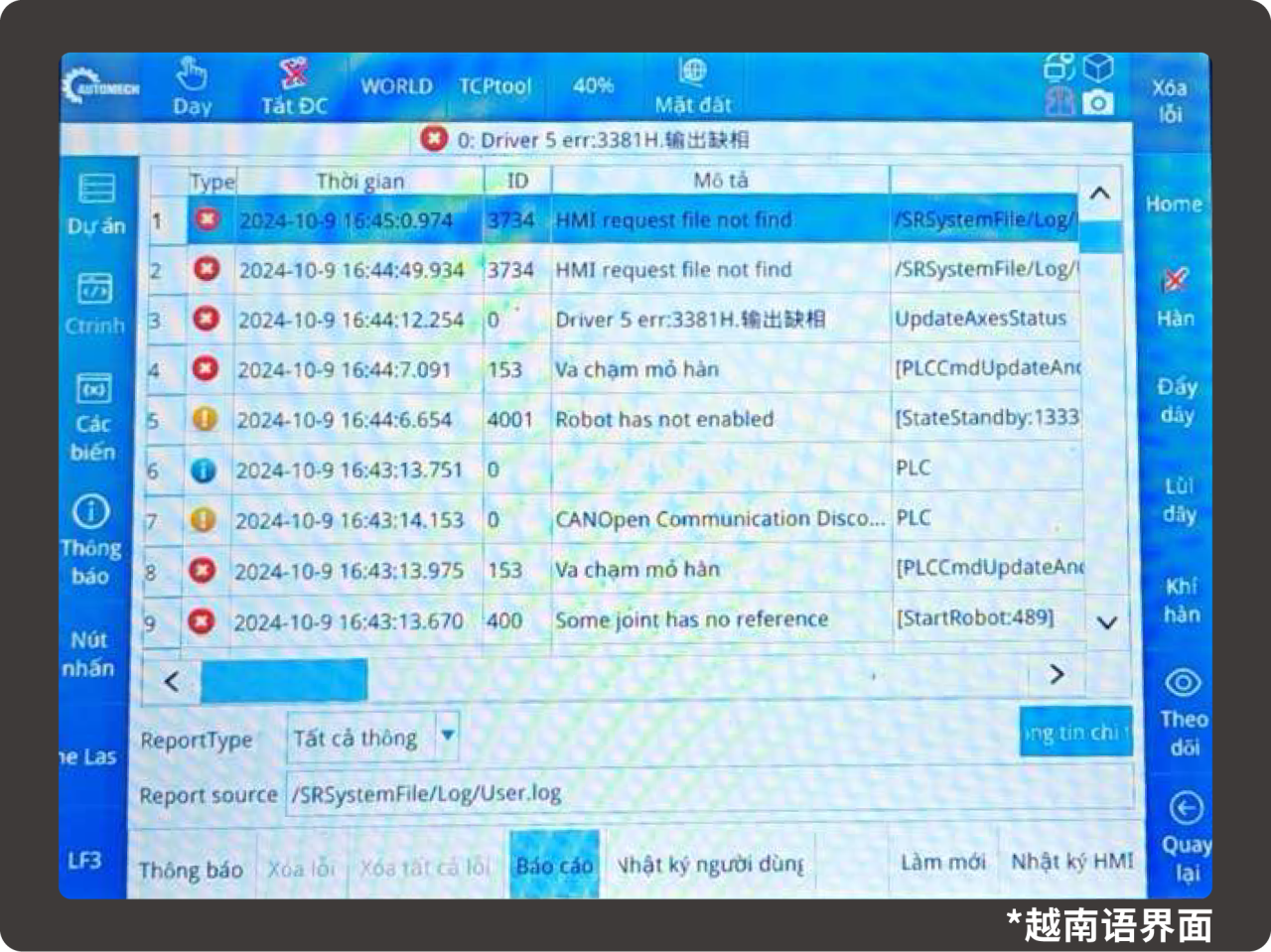
04|Logs
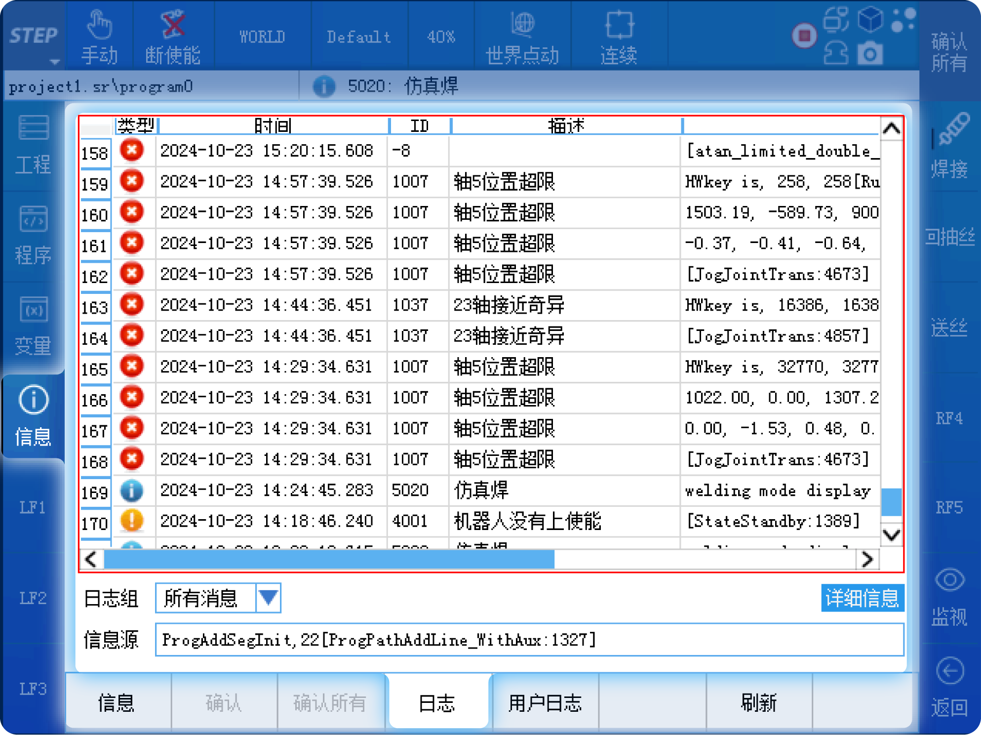
Click the “Info” button on the left to bring up the system log interface. The home page displays the current error messages. Clicking the “Confirm” button will clear the current error messages. Clicking the “Log” button will display the system’s historical fault information.
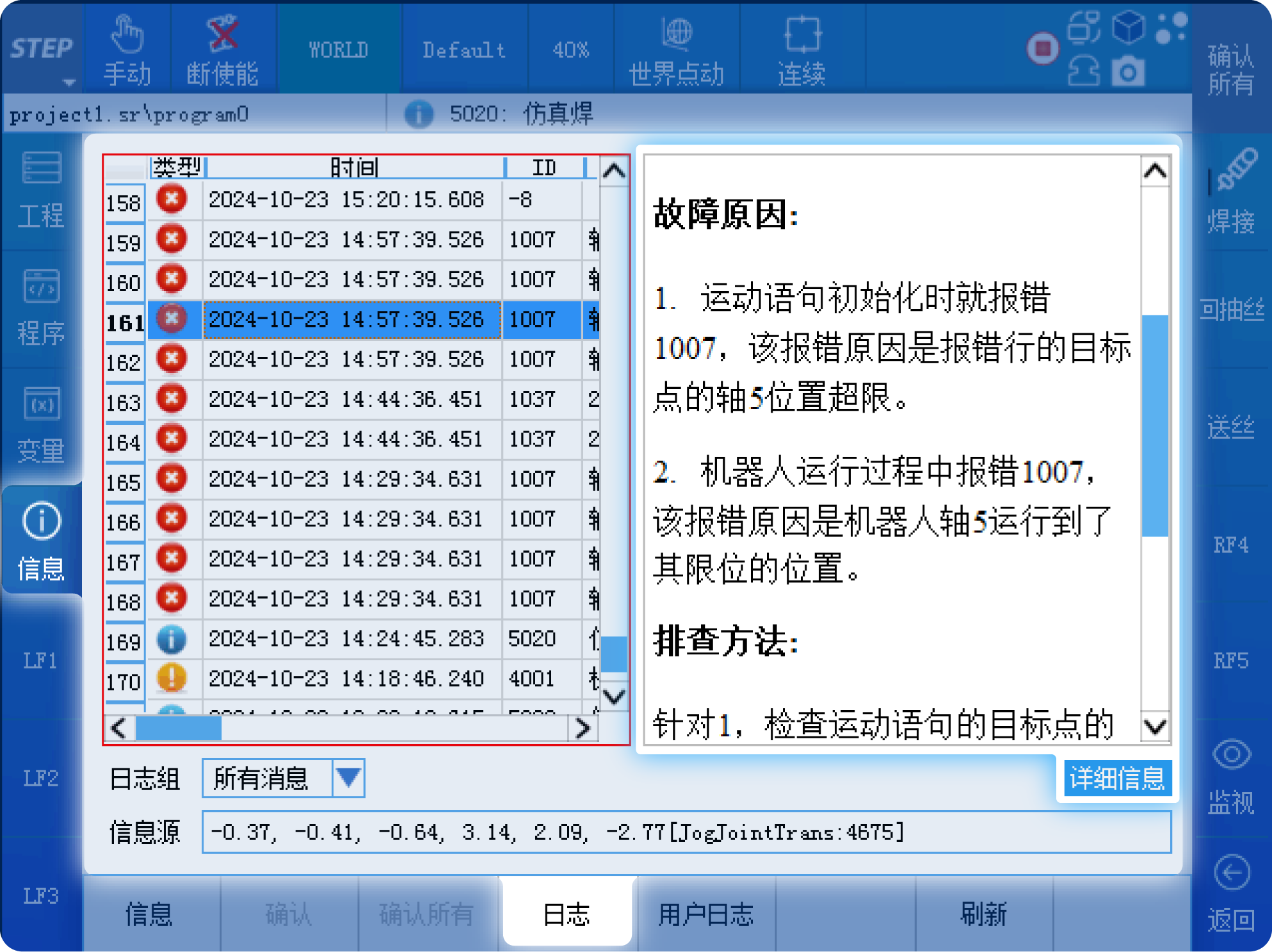
You can also view the cause of the fault and the corresponding troubleshooting methods by clicking the “Details” button.
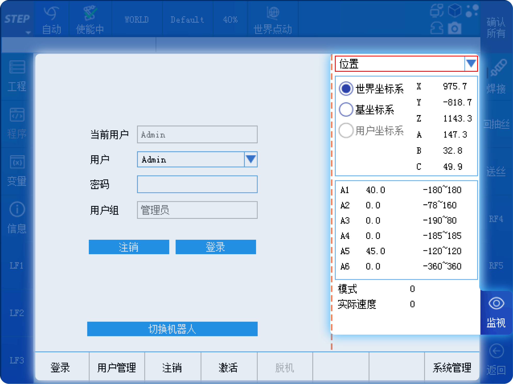
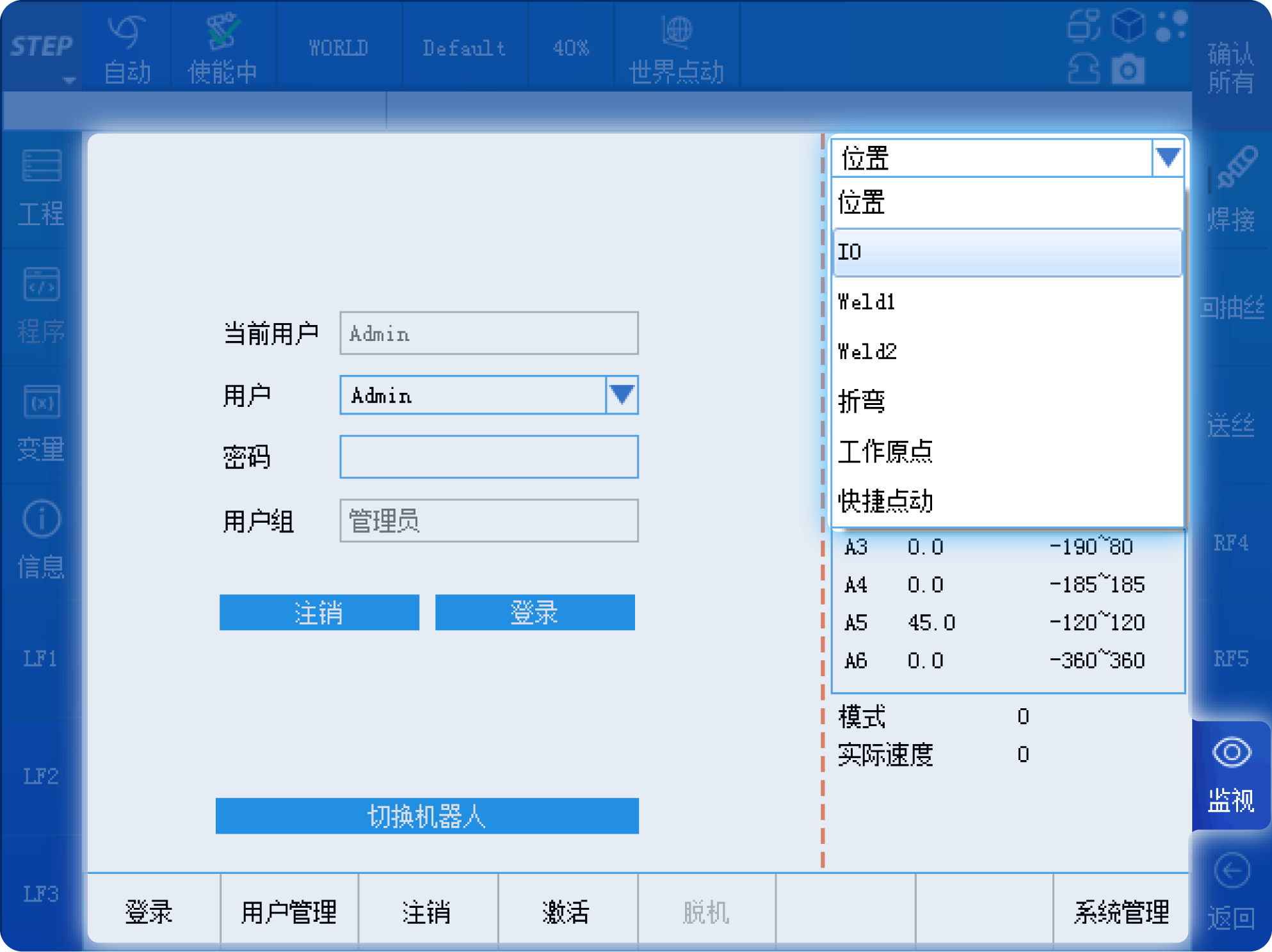
05|Surveillance
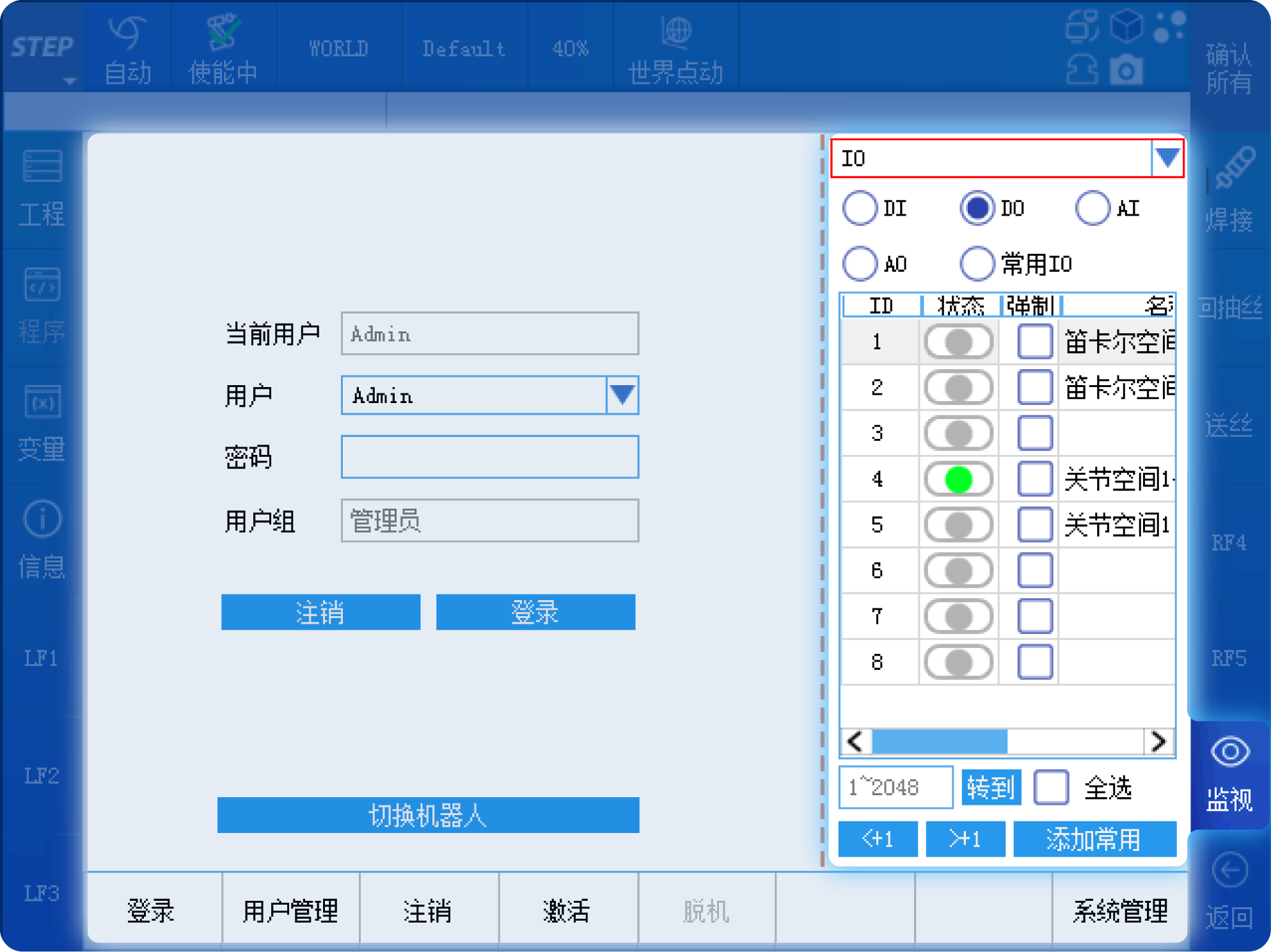
Click the “Monitor” button at the bottom right to view information such as the robot’s end-effector position and IO signals.
Select “IO” from the drop-down box to monitor the status of DI/DO and AI/AO.
06|Language Functions
By default, the system supports both Chinese and English, and also allows customization for other languages. You can access the language interface via Menu Bar > Control Panel > Language, where you can select among English, Chinese, and other languages. The selected language takes effect immediately. When you choose “Other,” the system displays the customized other language.
To customize other languages, you need to translate the files in the system’s language folder into the customized language and import them via the HMI replacement method. At the same time, you also need to translate the description content from the instruction comment files, error description files, teach pendant pop-up error files, and welding error files into the customized language, place them in the system’s designated directory, and then restart the robot for the changes to take effect.
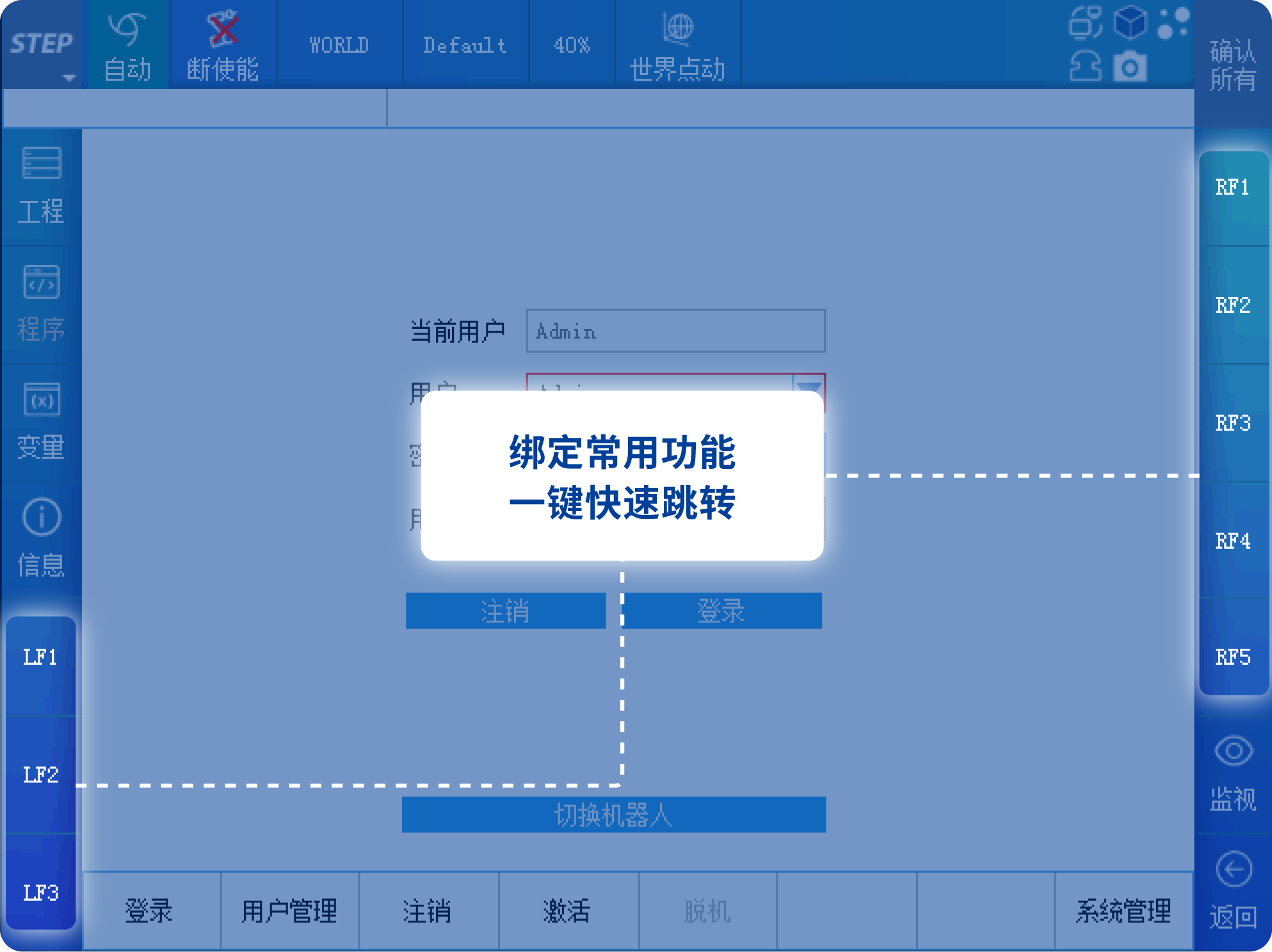
07 | Shortcut Key Function
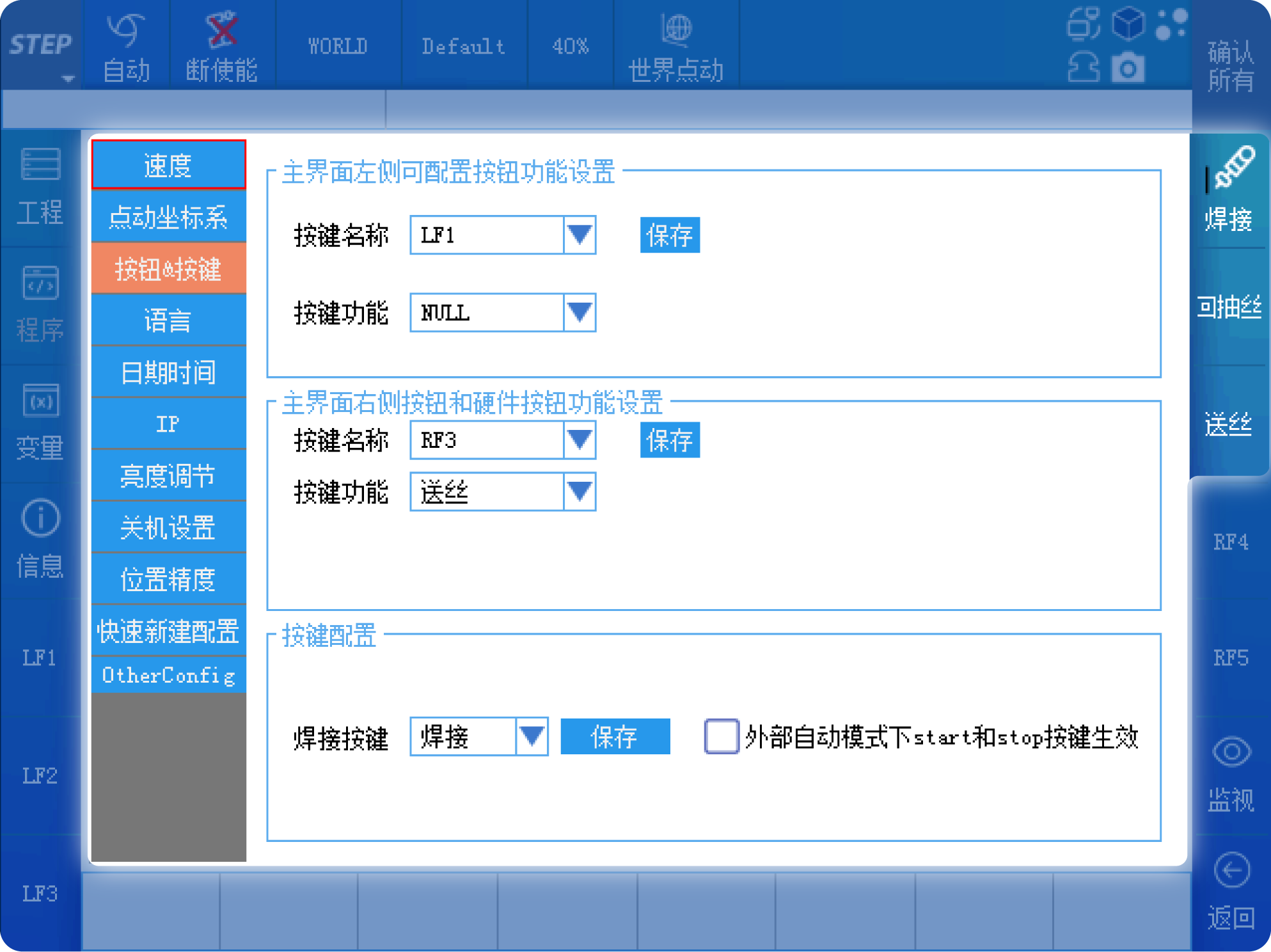
Finally, let me introduce the shortcut key functions on the left and right sides. When on-site programming requires frequent use of a particular function, you can assign that function to a shortcut key for one-click operation, thereby improving programming efficiency. On the left side of the interface, there are three shortcut keys: LF1, LF2, and LF3; on the right side, there are five shortcut keys: RF1, RF2, RF3, RF4, and RF5.
In welding applications, “simulated welding” is often used to debug robot programs. During the debugging phase, wire feeding and wire retraction are also frequently performed; therefore, these functions can be assigned to hotkeys for easy one-click activation.
Previous:

Contact Us
Email:
market@stepelectric.com
Address:
No. 1560, Siyi Road, Jiading District, Shanghai Municipality