
STEP Robot IO Signal Configuration
2024-12-13

Today, let’s learn together how to configure IO signals in the STEP robot operation software. IO signals play a crucial role in the industrial automation industry—they serve as the bridge for communication between devices and form the foundation for data acquisition and logical decision-making.
Signal Configuration
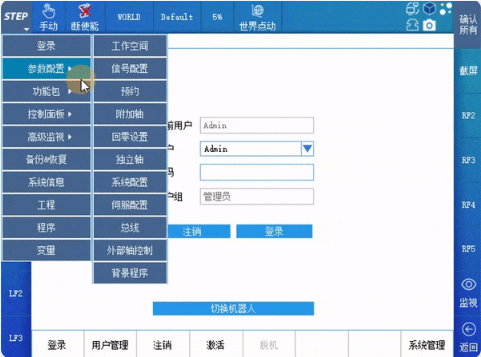
Click “STEP” > Parameter Configuration > Signal Configuration in sequence to enter the IO signal configuration interface, as shown in the figure below:
IO Configuration
The I/O configuration includes six configuration pages: DI, DO, AI, AO, GDI, and GDO. Among these, DI is used to configure digital input signals, DO is used to configure digital output signals, AI is used to configure analog input signals, AO is used to configure analog output signals, GDI is used to configure group digital input signals, and GDO is used to configure group digital output signals.
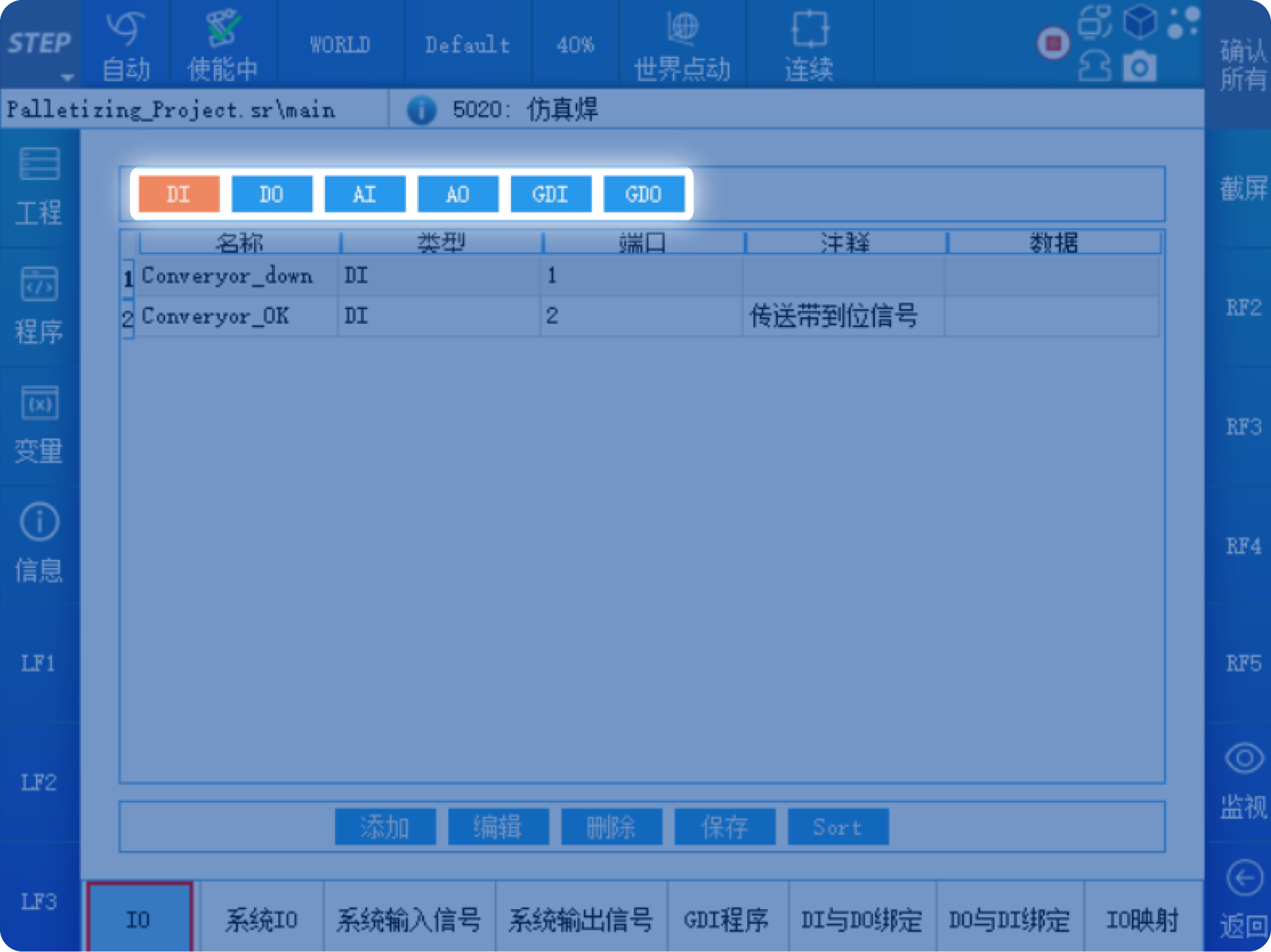
Select the DI page to enter the digital input signal configuration interface. You can configure up to 2,048 DI signals, with port numbers ranging from 1 to 2,048. In the DI configuration interface, the first column displays the name of the DI signal, the second column shows the type of the IO signal, the third column indicates the DI port number, and the fourth column provides comments for the DI signal. If a name or comment is too long to be fully displayed, you can drag the display box to reveal the complete name.
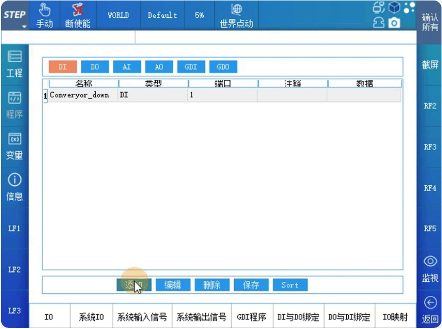
Click the Add button on the DI configuration interface, and an edit box for adding a DI signal will pop up, as shown in the figure below:
 Enter the name of the added DI signal in the Name field. The signal name cannot be in Chinese. In the Port Number field, enter the DI port number. The port number must not be one that is already in use—i.e., it cannot duplicate the port number of any other DI signal. You can enter a Chinese explanation of the signal’s meaning in the Comment field.
In the DI signal editing interface, you can modify the name, port number, and comments of a DI signal. If you no longer need a particular DI signal, select it and click “Delete.” A confirmation dialog box will appear; click the “Yes” button to delete it.
After modifying the configuration on the DI page, you must click Save for the changes to take effect; otherwise, the DI configuration will be invalid.
Click DO to enter the digital output signal configuration interface. You can configure up to 2,048 DO signals, with port numbers ranging from 1 to 2,048.
Click the Add button on the DO configuration interface, and an edit box for adding a DO signal will pop up, as shown in the figure below:
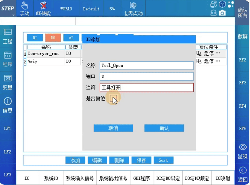 Enter the name of the added DO signal in the Name field. The signal name cannot be in Chinese. Enter the DO port number in the Port Number field, ensuring that the port number is not one that’s already in use. You can enter a Chinese explanation of the signal’s meaning in the Comment field.
In the DO signal configuration, there is a “Reset Option.” Clicking this checkbox will display the DO signal reset configuration interface. When conditions for resetting are met, the DO signal will automatically transition to the signal state selected in the reset data.
After modifying the configuration on the DO page, you must click Save for the changes to take effect; otherwise, the DO configuration will be invalid.
System I/O
Select the “System IO” option to enter the system signal configuration interface. By configuring the system I/O, it is possible to use external signals to control the robot's operating status and enable the robot to output its own status externally.
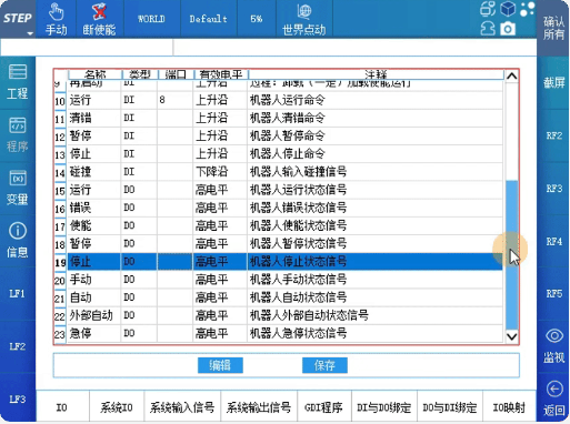
The default program requires configuring both the project and the program. Programs 1 through 4 require configuring the port number, the project, and the program; other signals only require configuring the port number.
When the default program configuration is complete and Programs 1 through 4 have no input signals, the external “Load” signal will automatically load the program configured in the default program. However, when there is a signal at the ports of Programs 1 through 4, the external “Load” signal will automatically load the program configured in Programs 1 through 4.
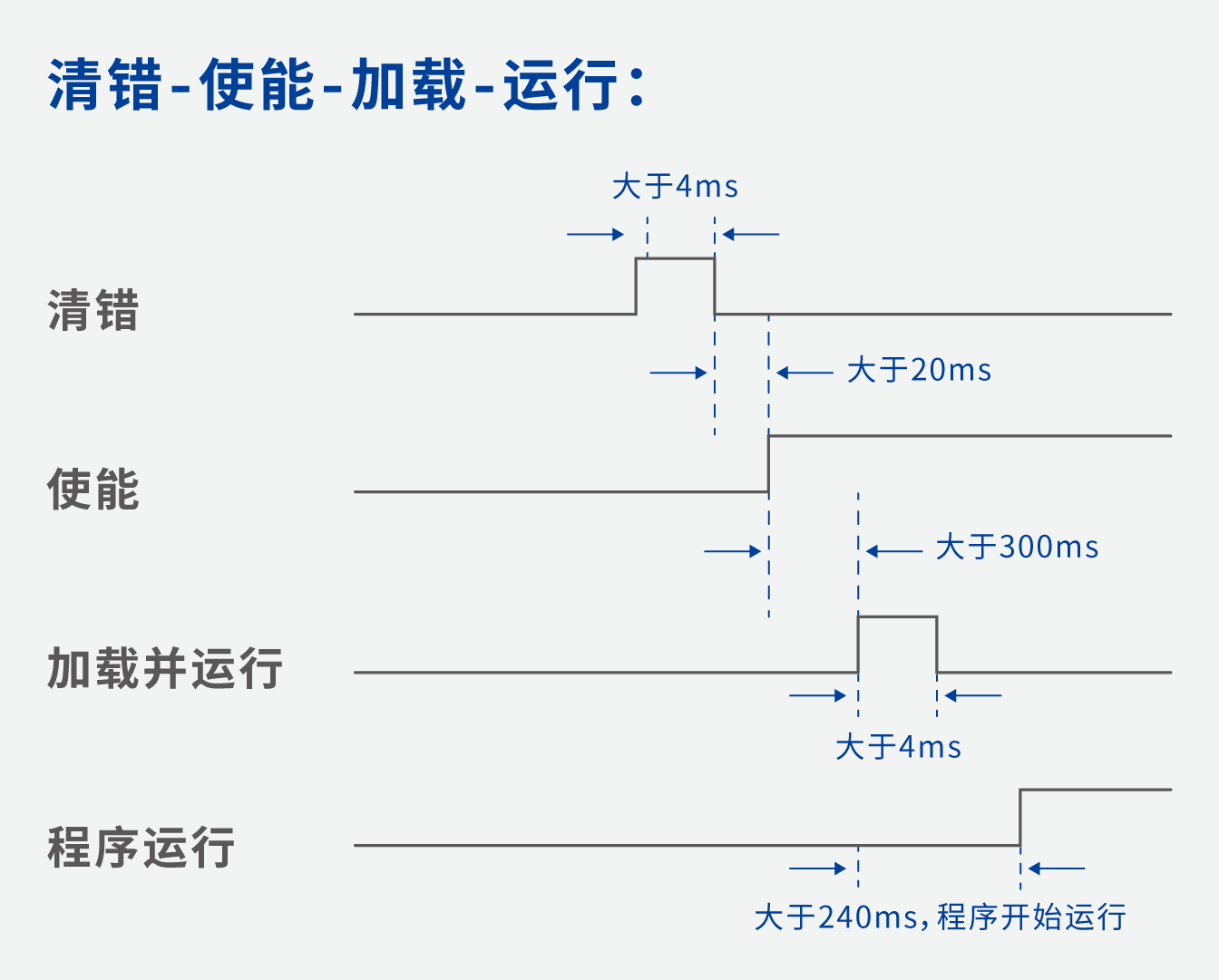
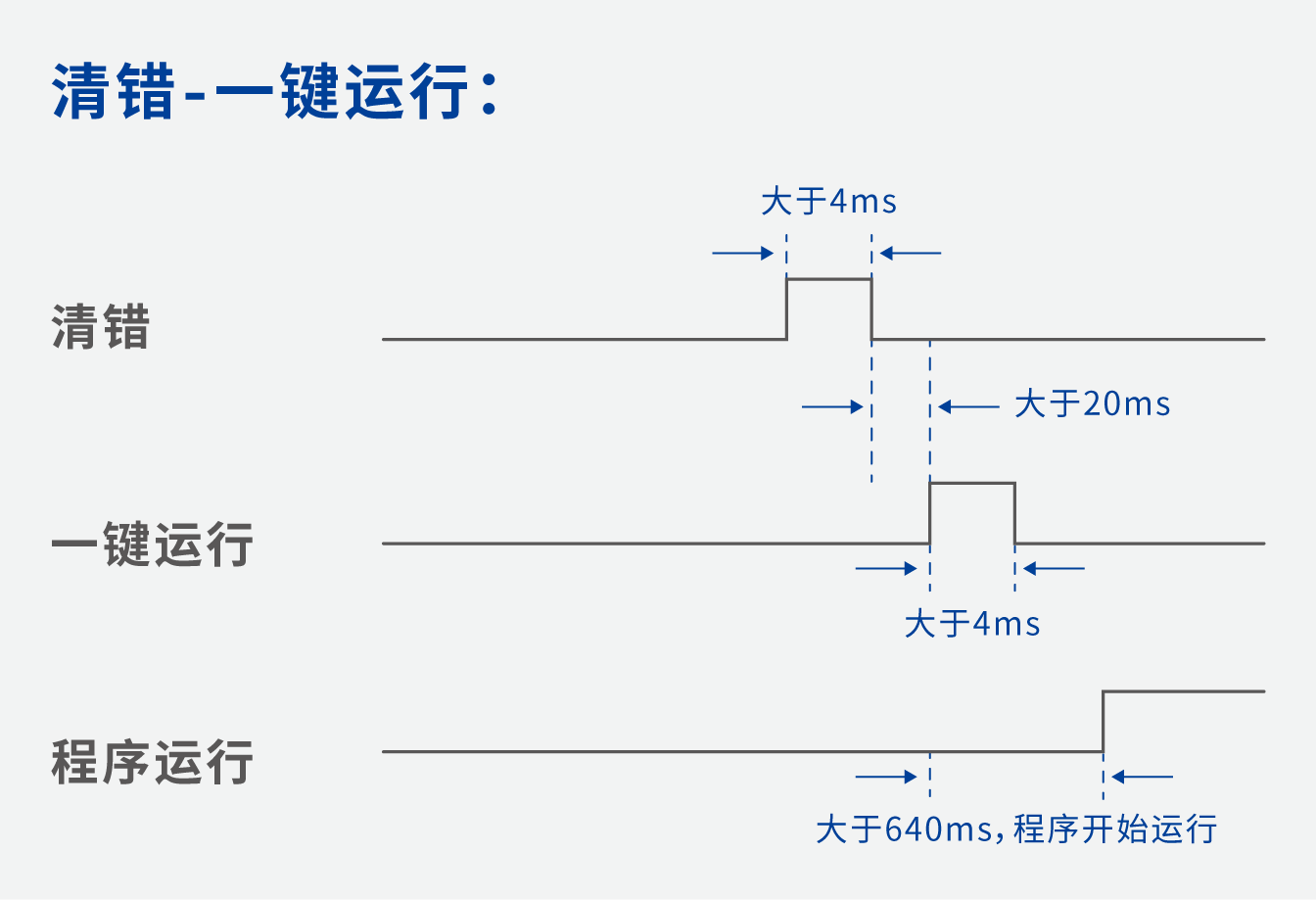
The robot startup sequence can be divided into two categories: programs that use "distributed operation" and programs that use "one-click operation."
The pause and run signals in the system signals take effect in both external automatic mode and automatic mode. In external automatic mode, when the program is started, the system signals’ pause signal and stop signal are checked. If either the pause signal or the stop signal is at a high level, the program cannot be started. In automatic mode, when the program is started, only the system signal’s pause signal is checked; if the pause signal is at a high level, the program cannot be started.
When the robot is running or loading a program, it cannot save the program. If you switch to another page without clicking the “Save” button, all previous configurations will be lost and you’ll need to reconfigure everything from scratch.
IO binding
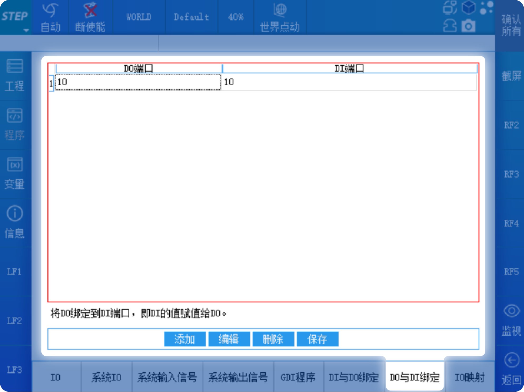
Using “DI-to-DO binding” and “DO-to-DI binding,” you can directly assign a DI value to a DO or a DO value to a DI without writing any program code.
For example: In the “DO-DI Binding” setting, if the DI port is set to 10 and the DO port is also set to 10, then when DI10 receives a TRUE signal, DO10 will also output a TRUE signal.
I/O mapping
Select the “IO Mapping” option to enter the interface for configuring IO logical relationships.
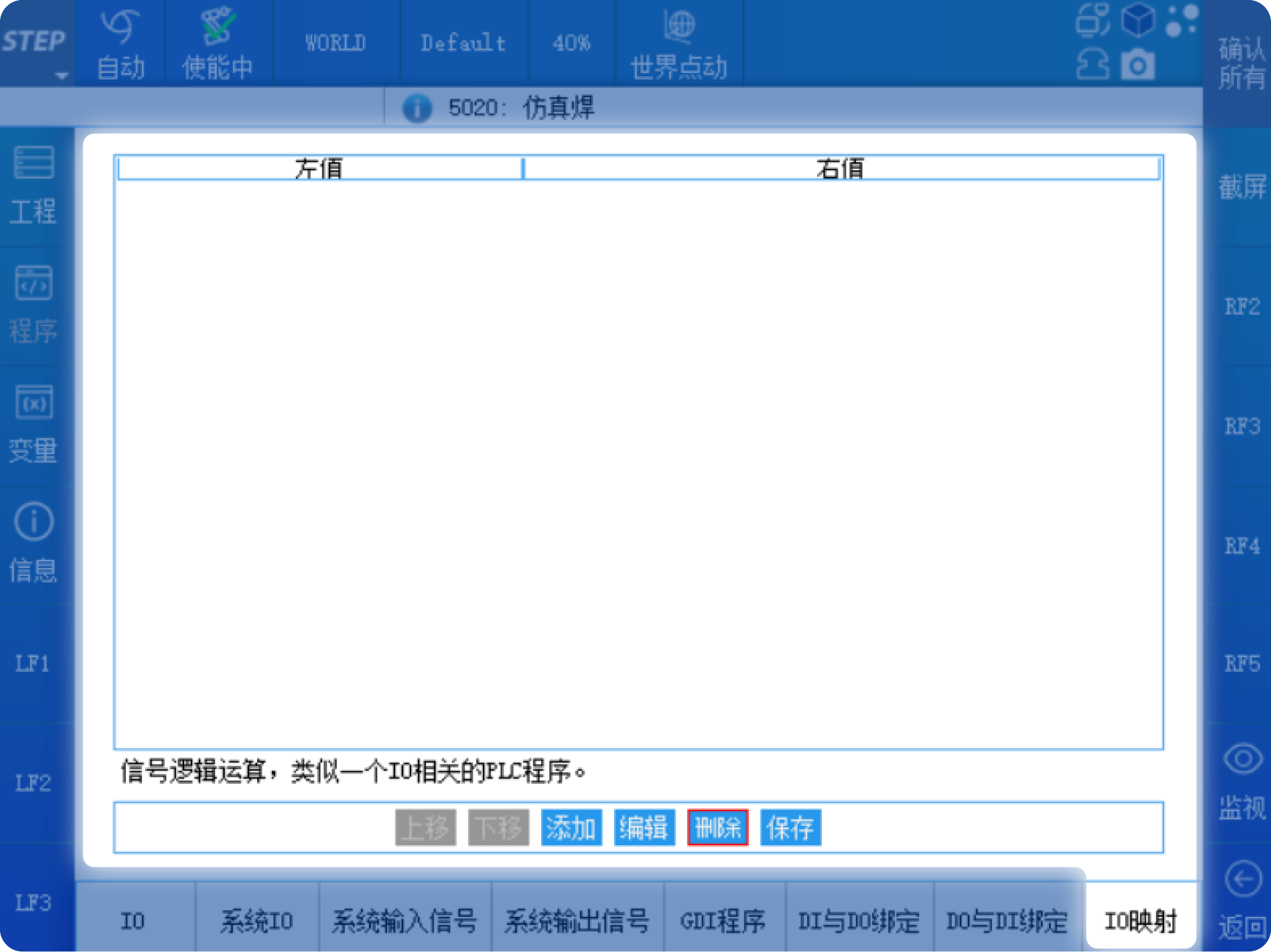
You can perform AND, OR, and NOT logical operations on DI and DO. For example, click the Add button at the bottom of the page to bring up the following pop-up window.
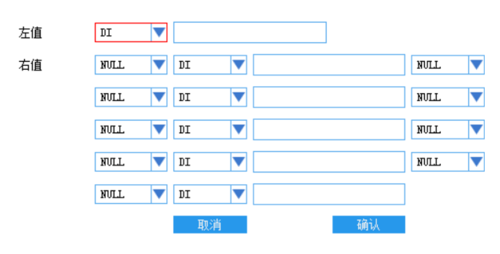 The left-hand side can choose either DI or DO, and then you enter the port number. Similarly, the right-hand side can also choose either DI or DO. You can use AND or OR logic symbols to combine the values of up to five DIs or DOs, and you can invert each individual DI or DO. Finally, an expression is generated and assigned to the left-hand side, as shown in the figure below:
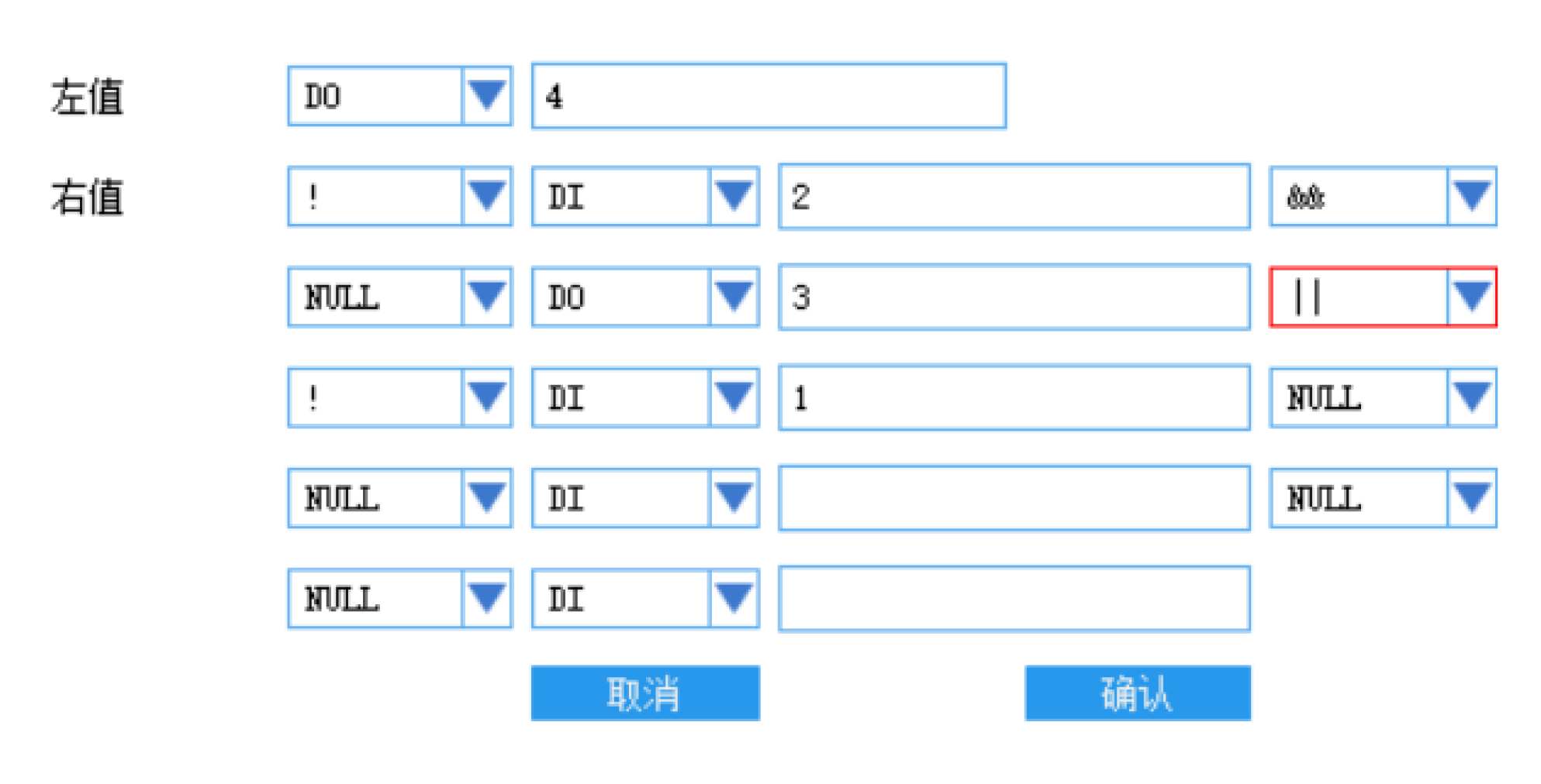
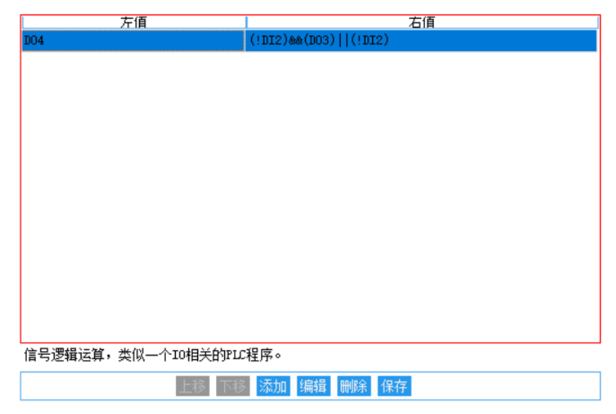 The operation in the first row of the table means taking the logical NOT of DI2, then performing a bitwise AND with DO3, then performing a bitwise OR with the logical NOT of DI1, and finally assigning the result to DO4.
I/O statement
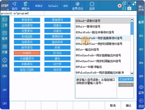
The STEP robot control system features a rich set of IO signal instructions. In the program, select "New," then click on the "IO Statement" option to locate these instructions. Choose the desired IO signal statement, and click "Confirm" to enter its configuration interface. After completing the configuration, click "Confirm" again to add the statement to the program.
6.1: Common Usage for Waiting for DI Signal Input
▉ DIWait(Converyor_OK,TRUE)
When the digital input signal Converyor_OK is TRUE, the program can proceed to the next line; otherwise, the program will keep waiting at that line.
▉ bool0 := DIWait(Converyor_OK, TRUE, int0)
When the digital input signal Converyor_OK is set to TRUE within the specified time int0, the program jumps to the next line and bool0 is set to TRUE. If Converyor_OK is not set to TRUE within the specified time int0, the program also jumps to the next line, but bool0 is set to FALSE.
6.2: Common Usage of DO Signal Output
▉ DOPulse(Conveyor_run,TRUE,Ms2000)
Set the DO signal Converyor_run to TRUE for a duration of 2,000 ms. The DOSet statement is used to set external DO ports to a specified value. For example, DOSet(Converyor_run, TRUE); sets the value of the port associated with the signal Converyor_run to TRUE. For more details on how to use IO signal statements, refer to the STEP Robot User Programming Manual.

Contact Us
Email:
market@stepelectric.com
Address:
No. 1560, Siyi Road, Jiading District, Shanghai Municipality