
STEP Robot Zero-Point Function
2025-04-07

To both new and existing users of STEP robots, it’s time for another installment of our Robot Classroom! In this session, we’ll provide an in-depth explanation of the “Zero-Point Function” of STEP robots, helping you make even more efficient use of your equipment.
This issue’s content is divided into three key sections:
• What key information does the zero-point data include?
• Where exactly is the home position of a STEP Robot at the factory?
• After losing a zero, how can you handle it quickly and efficiently?
Learn something “new”—start now!
Key content of Zero Point Information
The zero point is one of the key factors affecting the precision of industrial robots. If the robot’s zero-point information is incorrect, it will not only significantly reduce positioning accuracy but may also cause the robot to malfunction altogether.
First, we need to clarify the specific composition of the zero-point information. The position information of each joint axis (including any additional axes) of an industrial robot is provided by encoders, and when combined with the reduction ratios of the respective joint gearboxes, they collectively constitute the robot’s zero-point information. Encoders can be categorized into incremental encoders and absolute encoders. In practical applications of industrial robots, most systems use absolute encoders—and the STEP robot is no exception. Moreover, since gearboxes are fixed hardware components that rarely change in actual production, their reduction ratios can be regarded as stable reference values.
In the robot’s zero-point information, the encoder parameters required include the encoder bit resolution, single-turn information, and multi-turn information. The higher the encoder bit resolution, the greater the precision and the higher the resolution. Currently, most encoders used have a bit resolution of 20 bits. A 20-bit encoder has a resolution of 1,048,576 (2 to the power of 20) and a precision of 0.000343 degrees (360 divided by 1,048,576). To convert this into robot precision, the value must be divided by the corresponding reduction ratio of the gearbox. Single-turn information is used to describe the current motor position (the 20-bit encoder reading range is from 0 to 1,048,576), while multi-turn information indicates how many complete revolutions the motor has made. Single-turn information is a physical reading that is unlikely to be lost as long as the motor remains unchanged, whereas multi-turn information relies on the encoder’s power supply to remain valid and is therefore more prone to being lost in practical applications.
Factory zero position
Before leaving the factory, each STEP robot’s main body undergoes calibration using specialized instruments and self-developed algorithms to precisely determine the zero positions and reduction ratios of each joint. This information is then stored in the controller, facilitating subsequent on-site recovery and reference. Therefore, newly installed robots on-site do not need to have their zero positions recalibrated.
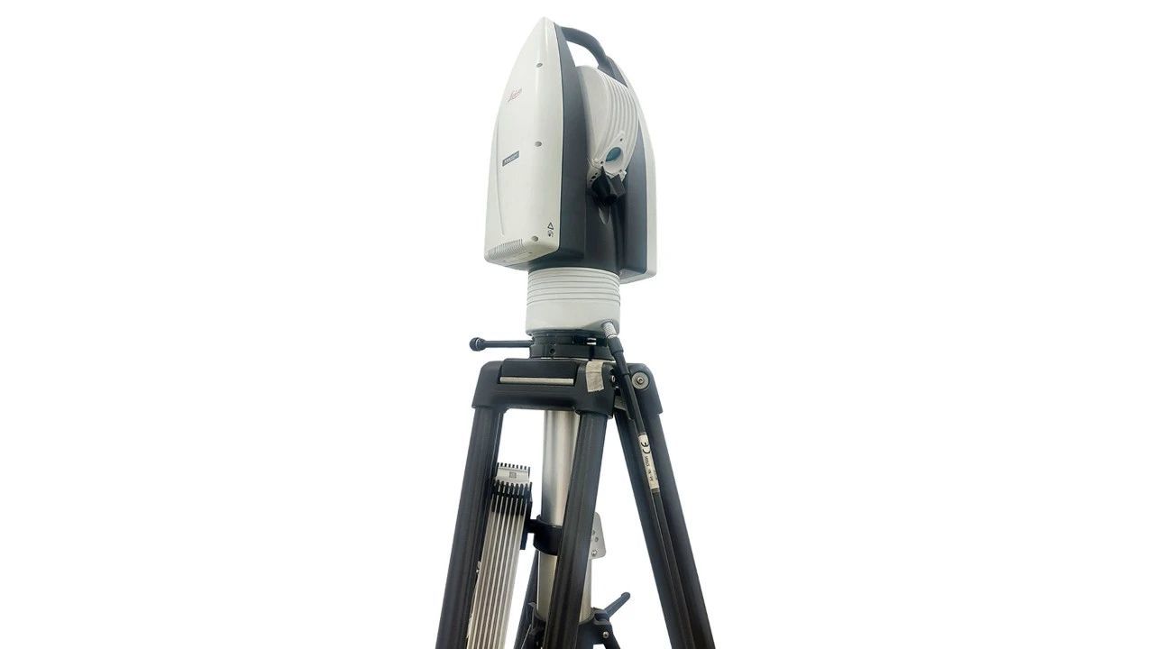
Calibrate the instrument
The precise zero point is located near the zero-scale line on each joint axis (though it does not necessarily align perfectly, since the zero-scale line is a theoretical mechanical reference line; typically, the actual calibrated zero point differs from the theoretical zero point by no more than 1°). The zero-scale lines generally take the form of holes or scale plates.
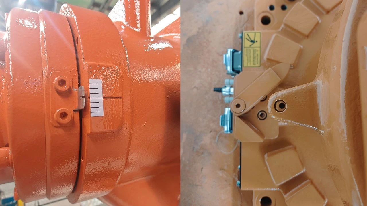

Schematic diagram of the zero-scale line
Zero-point recovery
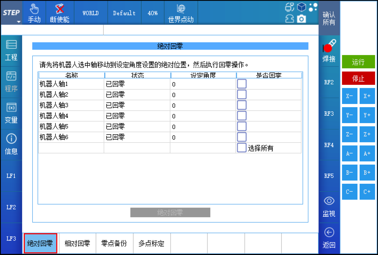
So, what should we do if the zero point is lost or the zero position becomes inaccurate on-site? The STEP controller offers four methods for handling zero-point recovery and ensuring accuracy: relative zeroing (zero-point fine-tuning), absolute zeroing, zero-point backup and restoration, and multi-point calibration. Each method is suited to specific causes of zero-point loss and delivers varying levels of recovery accuracy. To access the zero-point recovery function, go to the teach pendant menu: STEP > Parameter Configuration > Zeroing Settings. The password required is your login password.

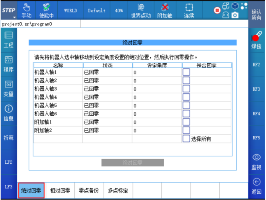
Zero-setting function interface
The following sections introduce various zero-setting methods and their respective applicable scenarios.
Relative zeroing
This refers to a precise zeroing method applicable when the encoder’s single-turn information is intact but its multi-turn information has been lost. This method modifies only the encoder’s multi-turn value, enabling the joint’s zero position to be restored to its factory-precision level.
This issue commonly occurs when the device has been left unpowered for an extended period, the battery is depleted, or there are loose or abnormal connections in the battery cable or encoder connector cable. After powering on, the teach pendant may display error messages such as “Battery Disconnected” or “Some axes lack reference.” In such cases, you can manually rotate the robot’s joint axes to align them as closely as possible with the zero-position scale markings. Then, using the relative homing plus fine-tuning-to-zero function, you can precisely determine the multi-turn values. (For detailed operating instructions, refer to the software manual—same applies hereafter.)

If the initially detected multi-turn value is inaccurate, after moving the robot back to the joint’s zero position again, you’ll notice a significant discrepancy between the actual position and the zero-scale mark on the joint axis—or alternatively, move the robot to a specific work reference point used in production. Taking the joint axis with a speed ratio of 100 as an example, a one-unit difference in the multi-turn value will result in an angular deviation of 360°/100 = 3.6° at the zero position. At this point, you can use the zero-point fine-tuning function to adjust the multi-turn value incrementally, unit by unit, and then re-verify whether the corrected multi-turn value is accurate. Typically, two iterations are sufficient to find the precise multi-turn value and thus determine the factory-zero point.
Tip: A dead battery is a very common cause of zero-point loss. When the voltage is low, the device will display an error upon startup; however, the zero point hasn't actually been lost at this stage. After clearing the error, the device can operate normally—but you should also replace the battery promptly. You can replace the battery while the robot is powered on, ensuring that the zero position is not lost.
Absolute zero return
Absolute zeroing is a zeroing method in which both the single-turn and multi-turn values of the encoder are modified. It is particularly suitable for applications such as customizing joint zero positions, replacing motors, or changing transmission components.
Customizing the joint zero position often occurs during debugging. To ensure that the robot’s world coordinate system’s XOY orientation aligns with the workpiece orientation, you can manually adjust the absolute zero position of the robot’s axis 1. The zero positions of axis 1 and axis 6 (or the end-effector axis) in industrial robots do not affect the robot’s absolute positioning accuracy.
If you’re replacing the motor or transmission components, it’s best to record the angles of each joint axis before replacement whenever possible. That way, after replacement, you can precisely return each axis to its recorded angle, ensuring that the factory-set zero-position accuracy is maintained. If it’s not feasible to record the current angles of the joint axes, then after replacement, you’ll have to rely solely on the zero-position scale markings to achieve absolute zeroing. However, when replacing hardware components, it’s uncommon for all axes to be replaced simultaneously; therefore, you should record and subsequently restore the angles of the other axes as well.
Tips:
1. Absolute zeroing is also the last method of returning to zero, used when none of the other methods can reliably locate the exact zero position.
2. When on-site applications require the robot’s six axes (or end-effector axis) to rotate over a wide range with extremely high rotational accuracy, and the current robot cannot meet these requirements, you can directly perform a secondary correction of the reduction ratio for the six axes (or the end-effector axis) on the teach pendant, and verify the rotation in increments of 360°.
Zero-point recovery
Zero-point recovery, as the name suggests, is a method for retrieving the precise zero point by using the zero-position information already backed up in the controller. It is suitable for situations where the loss of the zero point is caused by software malfunctions, such as encoder counting errors or multi-turn encoder errors, as well as when the drive needs to be replaced due to a drive failure, or when the controller itself fails and a backup of the controller’s data is available. The operation is simple and can be performed with a single button press at any pose of the robot.
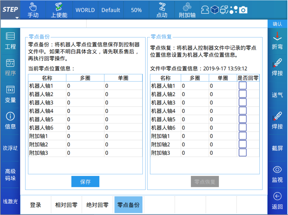
In Zero-Setting > Zero-Point Backup, you can view/save the current zero-point information, as well as view/restore the zero-point information stored in the controller. This feature makes it easy to compare multi-turn and single-turn values to ensure they match one-to-one. It also provides a straightforward way to check whether single-turn values have been lost before performing relative homing. Before each robot leaves the factory, its zero-point information is backed up. If the zero position has been modified during on-site operation and you’ve confirmed that the changes are correct, you should also back up/save the zero point here.
Multi-point calibration
The preceding description has covered how to re-establish the robot’s zero point. However, once the zero point has been confirmed as accurate, there will still be deviations in the robot’s absolute positioning accuracy and trajectory accuracy during actual applications (such deviations are inherently present in any robotic system—though their magnitudes may vary). So, are there any other methods available to further improve these accuracies? The answer is yes: multi-point calibration.
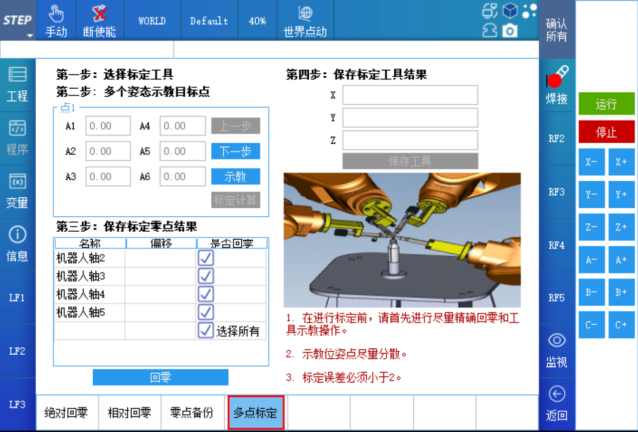
Multi-point calibration is a method that, after teaching the robot to assume more than 10 different poses at the same position, uses an internally developed algorithm to perform optimal solving, thereby determining the current robot’s zero-point deviation and tool deviation. It is a simple and efficient approach for improving the absolute positioning accuracy of the robot’s end-effector—particularly when the robot’s end-effector is equipped with a specific tool—in field applications. The operation of multi-point calibration is similar to that of the four-point tool calibration method; however, it requires aligning the reference points in more diverse poses, and the pose changes between each point should be as large as possible and evenly distributed within the robot’s operational range.
If the end effector of the on-site tool does not have sharp features, you can replace it with a new tool and perform multi-point calibration using the new tool (Note 1). After calibration is complete, correct and save the robot’s zero-point information, then replace it with the production tool for use.
If the end of the on-site tool has sharp features, such as a welding torch, use this production tool to perform multipoint calibration (Note 1) and obtain the corrected zero-point information and tool information.
Above, the robot’s absolute accuracy will all be improved.
Note 1: Whether using existing tools or new tools, before performing multi-point calibration, you should ensure that the robot’s current zero-point information is as accurate as possible, and the tool itself must first be calibrated using the four-point method.

Contact Us
Email:
market@stepelectric.com
Address:
No. 1560, Siyi Road, Jiading District, Shanghai Municipality