
STEP Classroom | Debugging Steps for the C7000 Elevator Integrated Control Cabinet (Taking NSPD04 Program as an Example)
2018-10-29
")
The C7000 elevator integrated control cabinet is the most widely used product recently introduced by STEP in the market. The mobile app version of “C7000 Debugging Steps” provides on-site installation and maintenance personnel with convenient access to timely reference information.

Handheld operator
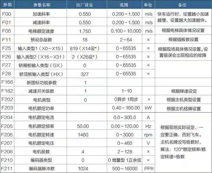
Parameters that need to be configured for slow trains
Wiring the control cabinet and the main unit
1. The elevator traction machine, steel cables, car, counterweight frame, and other components have been properly installed, and there are no obstructions in the hoistway.
2. Connect the power supply cables, including the three-phase input lines R, S, and T, as well as the output lines U, V, and W.
3. Connect the brake power cable properly.
4. Connect the all-in-one PG card AS.L06/U to the encoder cable from the traction machine, completing the connection while the power is off.
5. Insert plug-in board D0 into D1, and short-circuit the safety circuit and the door-lock circuit: 132-118, 118-116, 118-120, and 120-119 (short-circuit when a rear door is present).
Short-circuit the up/down speed switch C0M-84 and COM-86.
6. Short-circuit roof inspection switch COM-78A (T1-J01)
Basic signal confirmation
1. The safety circuit is enabled (X22 lights up), and the door locks are engaged (the main door lock X23, the front lobby door lock X24, and the back lobby door X25 light up).
2. The up/down speed switch is properly shorted, and X4 and X5 light up.
3. After resetting the fault, disconnect the power once. If the fault persists, troubleshoot it according to the error codes.
Slow train operation
1. When the up-line (X2 light) or down-line (X3 light) is under maintenance, the running contactor engages, and the system automatically learns the angle. After the learning process is complete, the main unit rotates at the maintenance speed.
2. If the maintenance running current is excessively high or fault codes such as 71, 91, and 115—indicating overcurrent—are reported, handle the situation as follows:
① Check whether the motherboard parameters F202-F211 are accurate.
② If the encoder is functioning correctly, the issue might be that the motor phase sequence is reversed; in this case, you’ll need to swap the connections of V and W.
③ Check whether the brake is open; if not, adjust it accordingly.
④ If the steel wire rope is not installed, the zero-speed PI value should be adjusted slightly downward.
⑤ For small-power integrated units with power ratings below 3.7 kW, the self-learning current may be too low and the phase angle inaccurate. After changing F307 to 280%, power up and run the unit again.
3. If the slow-speed train is running in the opposite direction from its actual direction, change F234 (motor phase reversal) from 0 to 1. F233 = 1 and cannot be modified.
Confirm the ahead signal for the express train.
1. The elevator’s mechanical installation is complete, and the safety and door-lock systems are properly connected and functioning normally (all jumper wires have been removed).
2. Confirm the status of the level signal and the deceleration switch.
① Confirmation of normally open and normally closed leveling signals: When the elevator arrives at a non-leveling position, if neither X6 nor X7 is lit, set the up-and-down leveling signals in F25’s input type to normally open “-”; if both are lit, set them to normally closed “*”.
② Confirmation of the installation direction for the flat-floor signal: When the elevator is undergoing maintenance and running upward, contact X7 will operate first, followed by X6; when running downward, the sequence of operations is reversed.
③ Deceleration switch confirmation: During maintenance, when the elevator moves upward and hits the upper deceleration switch X4, X4 should turn off and remain off until the elevator reaches the top floor. When the elevator moves downward and hits the lower deceleration switch, X5 should turn off, and X5 should remain off until the elevator reaches the bottom floor.
④ When the door opening switch is activated in advance, the door zone X14 (which must be set as a normally closed contact) should remain unlit at the leveling position but light up when the elevator leaves the leveling position. If this does not match, check the wiring of the car-top door zone switch according to the reference drawings. The car-top door zone switch must be wired to provide a normally open signal that is active at a high level.
3. Before starting the shaft learning procedure, connect the car communication cable and properly bridge the terminating resistor. Typically, set switch SW1 on car board 02G to ON (at this point, the resistance is 120 ohms). At the same time, the communication lights on both the car top board 02H and the car interior board 02G should be flashing simultaneously, indicating that the communication is functioning normally.
4. The door operator is functioning properly, the door-opening and closing actions are normal, and the wiring for the door-position detection signals is correct.
① Set the door operator to the middle position and monitor HX0 and HX1 via the operator (or observe them from the top of the elevator car). If both indicators show “*”, it means the contacts are normally closed; if both indicate “-”, it means the contacts are normally open.
② When the limit switch signal for the door mechanism is normally closed, after the door switch reaches its position: HX0 is “-”, and HX1 is “*”; after the door opens and reaches its position: HX0 is “*”, and HX1 is “-”. If there is a rear door, you must also confirm the limit switch signal indicating that the rear door has reached its position.
③ Normally open and normally closed states of other signals can both be monitored in this state, and then modified via parameter F28.
Fast train debugging operations
1. At any position (for example, if the elevator is at the 2nd floor with 2 stops, it must first reach the lower limit position before entering maintenance mode). In maintenance mode, access the self-learning menu for the hoistway. After confirming via the handheld debugger, switch back to normal operation. The elevator will automatically return to the 1st floor, then proceed upward, automatically measuring the height of each floor. Once it reaches the top floor and levels off, it will stop running. The operator will prompt you to verify whether the hoistway data is correct. Press Enter, and during synchronization with the host machine, the operator will automatically enter the UCM parameter settings. Adjust parameters M3 through M6 according to the actual situation. After completing the adjustments, on the M6 screen, press ESC and then Enter to exit. The operator’s registration command allows the elevator to run in fast mode; however, if you need to enable fast operation only when in maintenance mode, it could be due to improper installation distance of the deceleration switch. Refer to the recommended installation distance and make the necessary adjustments, then re-perform the hoistway self-learning process.
2. The operator can register the elevator to run at high speed, with single-floor, double-floor, and multi-floor operation on a floor-by-floor basis, and adjust leveling accuracy. The operator can also be plugged into the car panel for debugging purposes.
① F56 adjusts the upper-floor leveling (master adjustment): When the elevator is ascending, reduce the deceleration as it passes the leveling position; increase the deceleration before reaching the leveling position. F57 adjusts the lower-floor leveling (master adjustment): When the elevator is descending, reduce the deceleration as it passes the leveling position; increase the deceleration before reaching the leveling position. If the leveling distances for single-floor and multi-floor levels differ, adjust the F21 leveling error distance to resolve the issue.
② The operator enters “Parameter Classification” and finds “Leveling Fine-Tuning,” which allows individual adjustments for each floor. To adjust the leveling of each floor, use the operator’s left and right keys to switch between floors and make separate adjustments in two directions.
3. Outbound call setup: Connect the outbound call communication line and install the outbound call panel, setting the outbound address code for each floor.
① When the front door is opened, the lowest level corresponding to the first magnetic shielding plate is set to 1, the second level to 2, and so on.
② When opening the back door, set the lowest level corresponding to the first magnetic shielding plate to 49, the second one to 50, and so on; at the same time, change F123 to 1.
③ The bottommost display board layer is equipped with a terminating resistor (120 ohms). When the control cabinet is connected to the car communication cable, the total resistance becomes 60 ohms.
Comfort adjustment for reference.
a. The factory-set PI values generally do not need to be adjusted. Below are the empirical values: F212 = 160 (zero-speed P), F213 = 120 (zero-speed I), F226 = 0.8–1.0 (zero-servo time), F215 = 70 (low-speed P), F216 = 30 (low-speed I), F218 = 140 (medium-speed P), F219 = 25 (medium-speed I), F221 = 140 (high-speed P), F222 = 5 (high-speed I).
Tip: If the value is too high for a low-power host, it may cause oscillation; try reducing it.
b. If the elevator exhibits significant current noise during operation or experiences shaking during acceleration and deceleration, you can try the following encoder correction method: First, set the inspection speed F12 to 0.05; then, change F243 to 2. Press and hold the inspection up or down button until the elevator automatically stops, at which point F243 will automatically revert to 0. Alternatively, you can also try increasing the encoder filtering time in F232—typically to 5 ms.
c. In the elevator’s maintenance mode, with the door lock closed, enter the operator—perform debugging operations—learn the asynchronous motor, allowing the main unit to carry out self-learning. This will improve control performance (both synchronous and asynchronous motors can be used).
Precautions and Troubleshooting Methods During Debugging
1. During debugging, the door bypass plug must be inserted into the automatic operation (PL2) position; otherwise, the motherboard’s X26 indicator light will illuminate, and the system will report fault No. 8, preventing the slow-speed operation from starting.
2. The system reports Fault No. 38 immediately after power-on, or the UCMP fault is displayed on the operator’s screen when the brake opens during maintenance operation and immediately re-engages, triggering Fault No. 38.
① Parameter Settings: After the host brake detection switch is properly connected, observe whether lights on X10 and X11 on the mainboard are lit. If they are lit, change X10 and X11 in F25 to “*”; if they are not lit, set them to “-”.
② Signal Check: When the elevator stops, lights X10 and X11 should be on. Once the elevator starts running and the brake is released, these lights should turn off. If, upon stopping, lights X10 and X11 remain off, but the brake release light fails to come on, check the wiring or adjust the brake detection switch.
③ If the above parameters and signals are normal but a UCMP fault occurs, while in maintenance mode, simultaneously press and hold the up and down buttons (X2 and X3 will light up) for 5 seconds; the fault will then be cleared.
3. If, after the express train arrives at a station and the doors open, the main board displays faults 37, 45, or 54, confirm the following signal: After the express train reaches the correct floor and the doors are fully opened, the main board’s Y3 output will automatically generate a 0.5-second short-circuit signal to the door lock. Under normal circumstances, when the SM-11-A board is used to short-circuit the main door lock, this should function properly.
① The front and rear doors of the floor being reached open simultaneously, and one light on the X23 main door lock illuminates.
② Upon reaching the floor, only the front door opens; X23 and X25 light up.
③ Upon reaching the floor, only the back door opens; X23 and X24 light up.
④ F129 = 4 Set the third digit to “*”.

Contact Us
Email:
market@stepelectric.com
Address:
No. 1560, Siyi Road, Jiading District, Shanghai Municipality