STEP frequency converter | Coal mine belt conveyor master-slave control remote debugging
- Views:
- Time of issue:2020-12-08 00:00
STEP frequency converter | Coal mine belt conveyor master-slave control remote debugging
- Views:
- Time of issue:2020-12-08 00:00
The outbreak of the new crown epidemic this year has brought great inconvenience to the production economy in various places. It was originally planned to go to a coal mine in Ordos on February 15 to debug 3 main shaft belt high-voltage inverters. The work was also affected. If it cannot be put into production in time, it will affect the heating demand in some northern regions. Combined with the understanding of the actual situation on site and the consideration of the ease of use of STEP products, we decided to adopt an alternative solution - remote debugging.
1. The situation of the belt system of the main shaft of the coal mine
Original system configuration:
belt transport capacity: 1500t/h
belt: width 1400mm, strength ST3150, steel cord core belt
speed: 3.15m/s
transport length: 1110m
inclination: +16°
drive power: 3×710kW, frequency conversion drive
main motor voltage: 6000V
upgrade part: drive power increased from 3×710kW to 3×1000kW
This upgrade direction: expand production capacity, expand motor and frequency converter system, and the upgraded belt transportation capacity is expected to reach 2000t/h
2. On-site control plan confirmation
① The original system situation. The original system of the coal mine site is also driven by a high-voltage frequency converter. With the increase of production capacity, the original system can no longer meet the needs of production and transportation. The original system adopts a separate control scheme, and the three frequency converters are respectively given operating signals, and the operating frequency is manually adjusted. Torque balance.
② Transformation goals. The STEP inverter adopts the master-slave control droop function, the software automatically measures the output torque, automatically balances the power, and the output voltage and current of the slave are consistent with that of the master. Realize the automatic load balance of the frequency converter. The system control scheme is shown in Figure 1 below.
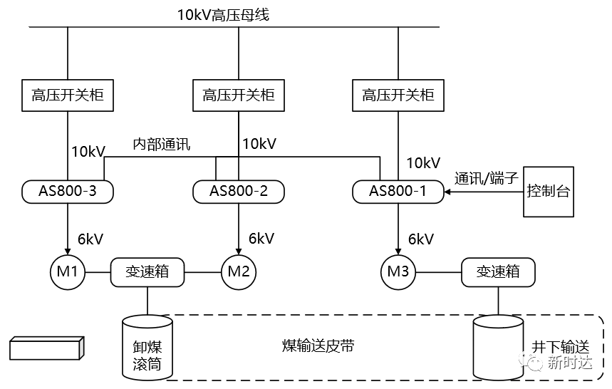
Figure 1-Master-slave control system diagram
3. Guiding on-site wiring
① Inverter internal wiring. It is mainly the connection line of the internal communication line of the inverter. Through remote guidance, the construction of the communication system required for debugging was quickly completed. The internal communication connection guide of the inverter is shown in Figure 2.
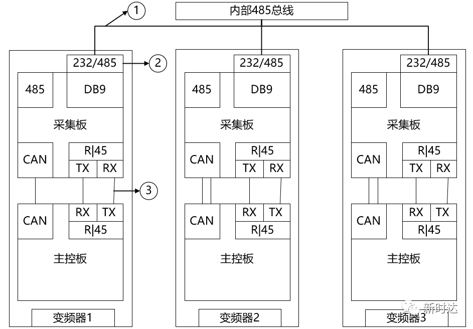
Figure 2 - Inverter internal communication connection
② External control line connection. Extract the control signals required by the user from the drawing, list the signals according to the signal type, mark the corresponding line number and the terminal number corresponding to the wiring position, and the WeChat video guides the user to complete the wiring of the control part according to Table 1.
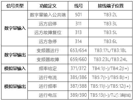
Table 1 - Inverter External Control Wiring
4. No-load test run
① Check the wiring on the high voltage side. Before the trial run, the WeChat video guides the user to confirm and check the wiring position of the inverter's incoming and outgoing lines.
② Inverter parameter setting check. Most of the inverter parameters have been solidified, and the master-slave control parameters have also been solidified to the multi-machine drive module, and the inspection is relatively smooth.
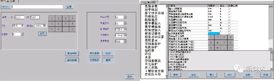
Figure 3-Inverter multi-machine drive parameter module Figure 4-Inverter parameter setting interface
③ Confirmation of the control logic
operation mode: After the console gives the start and stop command to the host, the host executes the start and stop at the same time, and the host controls the start and stop of slave 1 and slave 2 through internal communication.
Fault handling method: Any one of the 3 inverters will report a fault and stop, and the 3 inverters will make fault judgments through internal communication, and will be blocked by emergency stop at the same time.
Emergency stop processing method: any one of the 3 inverters is manually emergency stopped, and the 3 inverters make emergency stop judgments through internal communication, and the emergency stop is blocked at the same time.
④ Problems encountered in no-load trial operation and solutions
Host failure: The first high-voltage power transmission of the host reported that the uplink optical fibers of all power units were faulty. It was found that the uplink and downlink communication plugs were reversed when the optical fibers on the main control side were plugged in. The problem was solved after correction.
Slave 1 fault: When the master-slave control is linked, the slave 1 reports a unit block failure, check the internal communication cable of the inverter, replace it with a shielded wire, and solve the problem after adding grounding measures.
5. Test run with load
The user can use the coal produced in the underground inventory to carry out the on-load test before production. After the user console directly sends the start command to the host, the three frequency converters drive the main shaft conveyor to slowly transport the coal produced in the underground. It was successfully transported to the unloading area, and the test run with load was successful.
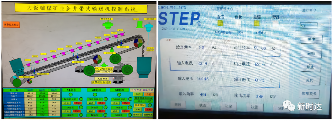
Fig. 5 - Operation console of user transport belt conveyor Fig. 6 - Operation interface of inverter host
6. Officially put into operation
Coal is a basic guarantee material to ensure people's livelihood. The coal mine responded to the call of the state to resume production in a timely manner during the difficult period of the epidemic, and the inverter was officially put into production and operation.
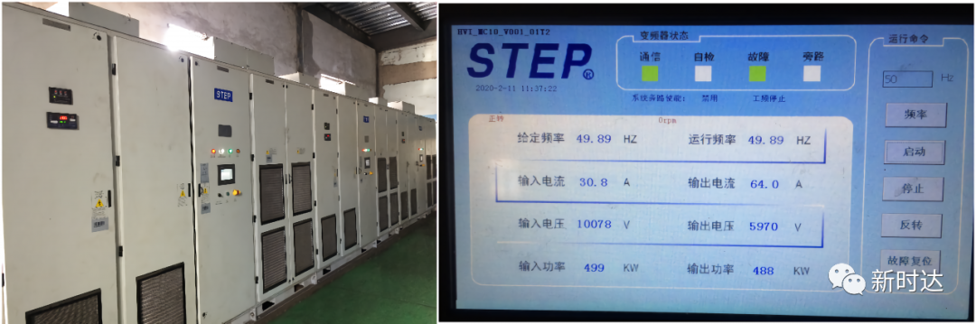
Figure 7 - The frequency converter is running normally Figure 8 - The main machine running interface of the frequency converter
Summarize
① This STEP high-voltage inverter constant torque output application has realized automatic load balancing. According to the user’s on-site feedback, in the original manual setting method, the output of the inverter is uneven, and the slave machine is often dragged to run in the power generation state, resulting in an overvoltage alarm. The belt is stretched and scrapped due to uneven force after 1-2 years of use. After the transformation, automatic load balance is realized, the service life of the belt is greatly extended, and the danger of burning the brake unit due to overvoltage of the slave machine is eliminated.
② The success of the WeChat video guidance and debugging this time has verified the ease of use of the STEP high-voltage inverter operation. At present, some inverters shipped out of the factory have realized free debugging. In the future, STEP high-voltage inverters can realize functions such as network online debugging and online fault diagnosis, and help the intelligentization of the industrial control industry. Writing a new chapter for remote services under special circumstances.
Scan the QR code to read on your phone
Contact Us
Electrical control:+86-400-820-7921 Variable frequency drive:+86-400-821-0325 Robot :+86-400-920-0275 Motion control:+86-021-3102 6318 Intelligent manufacturing:+86-021-6992 6005 E-mail:info@xinshida.com Address: No.599 Meiyu Road, Jiading District, Shanghai, 201802, China-
Business
-
Service
-
About
Swipe to follow STEP

STEP Service Number

STEP Subscription Number
©️ 2022 Shanghai STEP Electric Corporation ICP10024532-10