
Nikon debugging box

- Product Description
- Specification Parameters
- Download Materials
-
- Commodity name: Nikon debugging box
(1) Switch the EC power supply on the back of the tester to the INT position. (2) On the front panel of the tester, set the MODE to the encoder used for testing; the corresponding table for the encoder is as follows: (3) At the bottom-left corner of the front panel of the tester, set the switch to Analog Check. (4) Connect the 5V power supply to the rear panel. (5) Use a coupling to externally provide the test motor with a rotational speed exceeding 800 rpm and let it run. (6) Turn on the tester’s power supply to the ON position.
Product Introduction
Nikon debugging box
Features and Advantages
1. The wiring diagram is as follows:
2. Set the following before powering on:
(1) Switch the EC power supply on the back of the tester to the INT position.
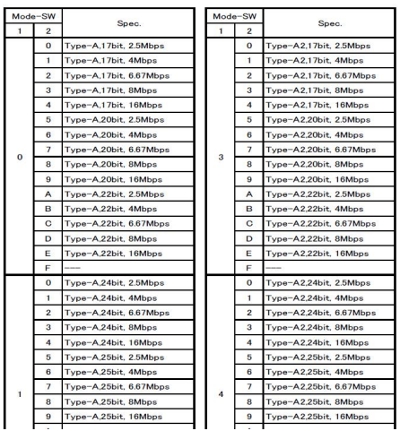
(2) Set the MODE on the front panel of the tester to the encoder used for testing; the corresponding table for this encoder is as follows:(3) Set the switch located in the lower-left corner of the front panel of the test machine to Analog Check.
(4) Insert the 5V power supply into the rear slot.
(5) Use a coupling to externally provide the test motor with a speed exceeding 800 rpm and let it run.
(6) Turn the power of the testing machine to ON.
3. Testing:
(1) Press the ECPOWER key to supply power to the encoder.
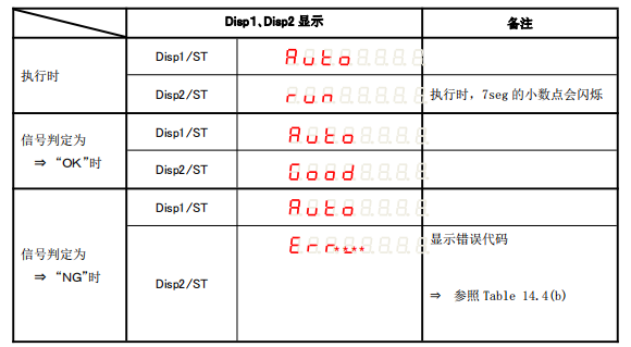
(2) Simultaneously press the SHIFT+F3 keys. The testing machine will start the test, and upon completion, the results will be displayed. The results comparison is shown in the figure below:
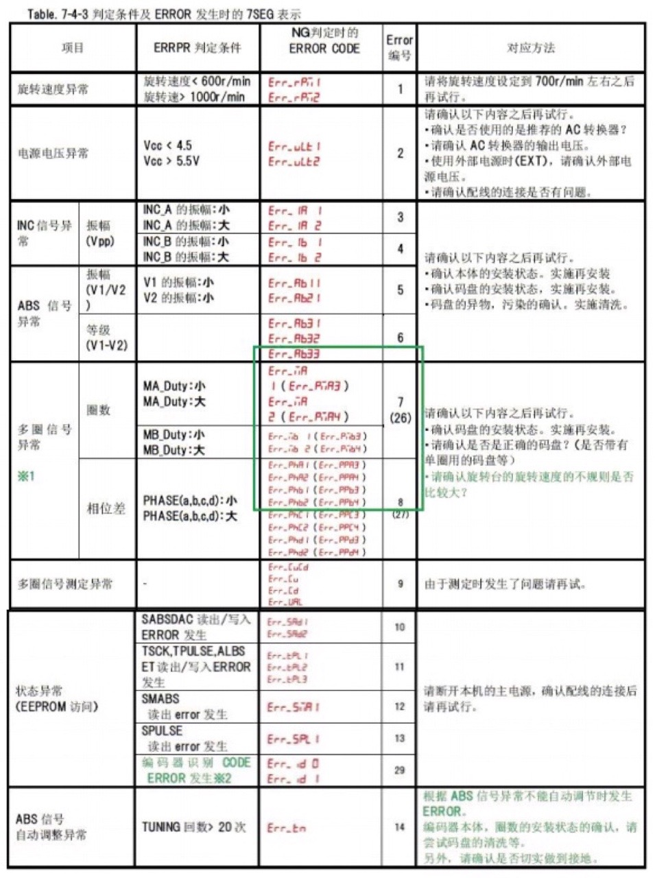
The error code is as follows:
Nikon test kit steps: Four images, corresponding from left to right.

Keywords:
Nikon debugging box
Product Category
Content update in progress,...